logo elektroda
logo elektroda
X
logo elektroda

T.amp TSA 4-1300 Power Amplifier Issue: Not Turning On, Red Diode Flashing, No Visible Damage

Matek920605 69321 346
ADVERTISEMENT
Treść została przetłumaczona polish » english Zobacz oryginalną wersję tematu
  • #271 20628417
    Ziemowit1973
    Level 13  
    Irons and kettle is a dummy charge???
    Congratulations on your recovery :)
    You can play with less power without any worries :)
    PS - at full power Peak Music Power Output for 8 ohms is 3600 watts per channel !!!
    ---
    1 - From another barrel - when you release a sinusoidal signal, the Clip diodes on the front panel light up at full power ???
    2 - 4 yellow diodes soldered directly into the board, they light up when you have full power ???

    I have original, operational transistors used IRGP4066-EPBF for this amplifier, i.e. the strongest ones !!! PM if anything

    Congratulations someone managed to fix it :)
  • ADVERTISEMENT
  • #272 20628867
    INtRO_Tech
    Level 14  
    Hello,

    Yes, it's a pity for the ears at home with this power, even in the bass, that's why irons and kettles went, and additionally a block of resistors with a resistance of 4 ohms in the water.

    Regarding your questions:
    ad.1 - yes, at full power, clips light up just before clipping, it scales nicely on different hits, always before clipping full power = clip.

    ad.2 - yes, the original diodes in the heat shrink on the motherboard light up practically on a par with the clip on the front panel, slightly earlier, but it doesn't bother.

    As for the original IRGP - great, but I prefer "my" version with lower power and security regarding power blocks :)

    ps. I still have the automatic fuse on the back of the housing to replace, from 24A to 12/16A.

    As for the work on the lows (bass) - everything has already been said, it is good, it lacks a bit of capacity to have a current reserve, but it is low and quite meaty. For information - the rev.1 disc (which works in this project) has a slightly shallower bass compared to the latest versions. On the hills, both versions work nicely, I compared the sound with different power amplifiers (and I have a lot of them) and nothing can be faulted ... apart from the exaggerated input sensitivity, with a slightly stronger potentiometer setting, it hums toto that hoho.

    Regards!
  • ADVERTISEMENT
  • #273 20684948
    procesor3d
    Level 12  

    >>19918050
    And would a power supply from several inverter welders be enough?
  • #274 20763462
    Robercikxxx
    Level 15  

    The original power supply is not defective in this amplifier, so you can just fix it. The most concerning thing about this amplifier is the lack of fuses for the power amplifiers. If someone has such an amplifier in repair, they know that whenever this power amplifier fails, one of the power channels and the power supply are always damaged. Why does the power supply also get damaged? You may ask. Precisely because this amplifier lacks original short circuit protection for power amplifiers. That means if the terminal transistors of a given channel burn out, the power supply has no current overload protection or fuses, and it simply has nothing to burn and the transistors explode. A switching power supply is not as flexible as a transformer to wait a few seconds when shorting transistors in either channel to throw off that 24A 250V thermistor on the back of the amplifier. I add fuses to the power supply, and in the event of a short circuit in any channel, these fuses should burn out. These fuses of mine have saved me twice already from repairing the whole power supply. Because I didn't notice that I had a burned power amplifier, and after putting the whole thing together, I turned it on and the fuses burned. I replaced them with slightly stronger ones and the same thing happened. So I took it apart, and it turned out that one channel was shorted.
  • #275 20764454
    aaanteka
    Level 42  
    Robercikxxx wrote:
    The original power supply is not a defect in this tip so you can just fix it.
    in this solution everything is defective, especially the way the power supply is implemented. It has been mentioned more than once in this topic.
  • #276 20764488
    Robercikxxx
    Level 15  
    What is wrong with this power supply according to a colleague, besides the fact that there is no current protection and no fuses?
  • ADVERTISEMENT
  • #277 20764624
    aaanteka
    Level 42  
    A colleague may be that someone without much of a clue put a few components together, and most likely copied a fairly common/unsuccessful DIY amateur design.

    The power supply completely fails to meet the parameters of a power supply for an acoustic amplifier, in total a power supply for four class H power amplifiers.

    But all this is already presented many times in the topic.
  • #278 20764638
    Robercikxxx
    Level 15  

    Well, I can see that my colleague simply does not like this power amplifier and maybe even the whole company. I would like to remind you that this amplifier is a budget power amplifier, which costs about 2700 PLN and it is not and will not be made of gold. If there were everything that should be in this amplifier, it would not cost so much. And it would cost two or three times as much. There are many things that are missing in this terminal, but let's not fool ourselves - this is not a Powersoft or Lab.gruppen terminal, which cost 5000 PLN and more. Every company makes minor and major mistakes. Man also makes mistakes, as they say, the one who does nothing thinks.
  • #279 20764668
    aaanteka
    Level 42  
    This is a branded Chinese product, not a brand of any kind.
  • #280 20863966
    arek59
    Level 29  
    I converted this converter into a half-bridge.
    I left the SG circuit, connected two IGBTs in parallel through the control transformer to the SG outputs, changed the paths at the IGBT accordingly, removed the large thermistor near the transformer, replaced it with 3 ceramic capacitors 1uf/250v in parallel, between the IGBT and the capacitors on the rail + I put a T15A fuse and that`s it. The amplifier has less power, but it goes down to 2 r and works without failures. Nothing even heats up.
    The power supply for H3 is 2x110-115v dc, it is enough.
    I recommend this modification as a last resort. It even worked on irfp460 for testing 😉
    One day I will add current protection for the power supply by placing a transformer in series and an appropriate SG configuration.
  • #281 20864453
    Robercikxxx
    Level 15  
    Do you have any photos of this conversion?
  • #282 21036937
    zbyszekdymny
    Level 12  

    What markings do the diodes in the IGBT gates have in this amplifier? It mainly concerns D750, D751, D752, D753, D205, D206, D207, D208 and the resistor R473. The final stages are operational, checked in the manner described on the forum, using replacement power supply from transformers, and work properly. Only the converter was wrinkled, the IGBT keys were opened so that their structures were visible, and of course the SMD diodes and a few resistors were closed and open, the rest of the elements were checked and appear to be functional. I replaced the IR2110S drivers, SG3525, and LM555 as well. I ordered the IGBT from a Chinese company. After assembling, I will see if it will stand up or explode.
  • #283 21036976
    Robercikxxx
    Level 15  
    R473 is the same as the THT resistor you installed, i.e. 47 Ohm. Diode D205, D206, D207, D208 is a 1N4148 diode
    Diode D750, D751, D752, D753 is a 15V zener diode
    In all the amplifiers I have repaired, NE555 and LM393 have never been damaged. Sg3525 sometimes happened to be damaged. If you ordered transistors from China, be careful because there are many fakes of this transistor. And the chance that you will buy the original is about 35%. Immediately measure the gate capacitance in the transistor when it arrives, between the first and third legs the capacitance should be about 4nf.
  • #284 21037032
    zbyszekdymny
    Level 12  

    Approx. Thank you very much for the quick answer, I will do exactly as my friend advises.
  • #285 21037036
    Robercikxxx
    Level 15  
    Please, if you have anything, write it down.
  • ADVERTISEMENT
  • #286 21049561
    zbyszekdymny
    Level 12  

    Well, the IGBTs have just come from China and after measuring the capacitance of the gate with the emitter, the result is, as Dear Colleague Robertcikxxx wrote, about 4 nF. So it would seem ok at first glance. It will turn out after washing. I put in the transistors and nothing, complete silence. The voltage on the main electrolytes is 315V, the auxiliary converter is working, the red and orange diodes on the board next to the capacitors are lit. The supply voltages of SG3525 and IR2110S reach and are at the level of 16.5V, but there is no waveform with SG3525 with legs 11 and 14, much less with drivers. The triac was replaced as a preventive measure. What else can block this converter? I will add that I turn on the converter with three 100W bulbs connected in parallel and in series between the network and the converter, so that there are no fireworks.
  • #287 21049572
    Robercikxxx
    Level 15  
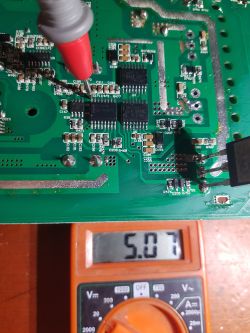
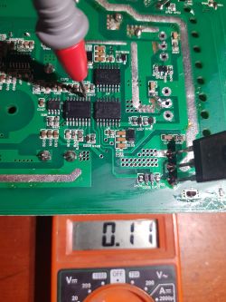
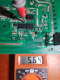
    Check what voltages you have at these points.

    Measuring voltage on a circuit board using a multimeter Voltage measurement on a circuit board using a multimeter. Measuring voltage on a circuit board with a multimeter.
  • #289 21050899
    zbyszekdymny
    Level 12  

    So. On the 16th leg of the SG I have 5.08V, on the tenth leg it is 5.04V, and it should be 0.11V. Just like my friend`s, and on the ninth o`clock I have 5.87V. So this one voltage is too high. Waveforms at the outputs 4, 5 and 7 of the SG3525 system. There is no signal at outputs 11 and 14.
  • #290 21050982
    Robercikxxx
    Level 15  
    You need to look for the problem on lm339 and ne555, there should be no 5V voltage on leg 10 of the sg3525 system. If you replaced the ne555 and lm339 chips, put back the existing ones.
  • #291 21052253
    zbyszekdymny
    Level 12  

    So I will, but tomorrow, because today I am already completely knackered. It is possible that fakes have hit.

  • #292 21053315
    zbyszekdymny
    Level 12  

    LM339 I did not replace, it is what it was and LM555 I replaced. I'll order both chips I'll solder them in and let you know what the results will be.

    .
  • #293 21063455
    matichem
    Level 11  

    hello, i need the value of the capacitors in the igbt suppression circuit, in series with 22 ohm. thanks.
  • #294 21063501
    Robercikxxx
    Level 15  
    150pF (pico farad) at 1000V housing
    smd 1206
  • #295 21063564
    matichem
    Level 11  

    Thanks mate, the resistor is probably for that voltage too, eh? Because the usual ones were burning the whole set, only I don't know if it wasn't sometimes because of the 100nf capacitor I had in the extinguishers.

    Otherwise I see that such resistors are hard to get.
  • #296 21065784
    Robercikxxx
    Level 15  
    No wonder it was burning you and in fact probably the resistor was burning you. Too much capacitance for that frequency or too weak a resistor, not enough power. And did you at least have this 100nf capacitor at a minimum of 600V ?
  • #297 21068970
    zbyszekdymny
    Level 12  

    I inserted this LM339 and the inverter got up. The amplifier started up correctly. I did a test under load and everything seemed fine for about 30 minutes. After turning the amp off and restarting, at first everything seems fine - the fans start up, the amp starts playing, and a reboot occurs - everything shuts down and turns on again, and so on and so forth. After checking what's gone wrong, I have one IR210S driver and one capacitor in the gasifier damaged, 22Ω resistors good. Is it possible that it is due to the lack of this capacitor that this IR could have failed? IGBTs working fine. After replacing the driver the inverter works, but I do not tire it without this incomplete gasifier. At the moment I don't have a capacitor of this value.

    Added after 31 [minutes]:

    Am I maybe bought these 15V zener and these 1N4148 diodes to putty? Although at the moment they are in working order. Perhaps a colleague can point out where he buys proven parts for his repairs? I wouldn't want to mess up the IGBTs as they seem OK as they lasted those 30 minutes of almost full load operation.
  • #298 21069235
    Robercikxxx
    Level 15  
    You can check the 4148 and the zener diode with a laboratory power supply with a current limit of 5mA or 10mA. It is difficult to find electronic parts at a reasonable price and they should be either original or fake but of good quality. I recently bought transistors on allegro, which were fakes of poor quality. It's not fun on Chinese sites either.

    Added after 3 [minutes]:

    2.65zl 8%OFF | 50 pieces 1206 SMD capacitor ± 5% 1000V C0G 22pF 47pF 68pF 150pF 180pF
    https://a.aliexpress.com/_ExIvmEj

    Added after 2 [minutes]:

    https://allegro.pl/oferta/rezystor-smd-22r-opornik-22ohm-5-1206-x100szt-7059049833
  • #299 21069977
    zbyszekdymny
    Level 12  

    Thanks, mate. I'm going to order the capacitors and buy those zener and those 1n4148s elsewhere, just to be sure. It's possible that this one driver was somehow defective, and it doesn't look original to me. I will write what happens after replacement.
  • #300 21080060
    zbyszekdymny
    Level 12  
    I replaced the capacitors in the extinguishers, one was crushed and not doing its job, so I replaced all 4 pieces with new ones, the diodes from D205-D208 1N4148 and the zener diodes for 15V from D750-D753 and that faulty IR2110S driver were also replaced. I wasn't sure about the quality of these diodes, so I ordered from another source and another manufacturer. Everything seems to be fine now. The amp fires up every time, plays correctly, and has undergone a baptism of fire at full load. Thanks to my colleague Robertcikxxx, I found out what the components in the IGBT gates should be and thanks to this the inverter was able to be repaired. In my case none of the 4 power amplifiers were damaged, only the inverter itself. All IGBTs, 47Ω gate resistors, 1N4148 diodes, 15V zener diodes, IR2110S drivers, SG3525 PWM generator and LM339 were damaged. Now there is nothing left to do but to expect the next explosion. Regards

Topic summary

The discussion revolves around issues with the T.amp TSA 4-1300 power amplifier, specifically its failure to turn on, indicated by a flashing red diode and no visible damage. Users share their experiences troubleshooting the amplifier, including checking the power supply, replacing damaged components like IGBTs, IR2110 drivers, and capacitors, and the challenges of finding schematics. The conversation highlights the importance of proper voltage levels, the need for fuses to prevent damage, and the potential for modifications to improve reliability. Several users report successful repairs after replacing critical components and adjusting the power supply configuration.
Summary generated by the language model.
ADVERTISEMENT