logo elektroda
logo elektroda
X
logo elektroda

T.amp TSA 4-1300 Power Amplifier Issue: Not Turning On, Red Diode Flashing, No Visible Damage

Matek920605 69543 346
ADVERTISEMENT
Treść została przetłumaczona polish » english Zobacz oryginalną wersję tematu
  • #61 18365297
    Matek920605
    Level 10  
    A complete change of power supply would definitely help :) although there are examples of these amplifiers that work without any reservations, unfortunately I do not know anyone who would have it, if only for comparison. I replaced the SG3525A and IR2110s again, the LED on the motherboard does not go out as before, it is on all the time. However, neither the relay nor the LEDs on the front panel turn on. As if the electricity was not going anywhere else.
  • ADVERTISEMENT
  • #62 18365378
    INtRO_Tech
    Level 14  
    You could develop an alternative junction using everything that is currently in the amplifier, I'm not sure but maybe something simple on the TL494 with the control of these IGBTs or replacement with cheaper MOSFETs? If I think wrong - please correct me.

    Kind regards
  • #63 18366161
    Michel424
    Level 14  
    I would join it, because in some time such a damaged end will come to me and it will definitely be an A converter due to the fact that when it comes to the smd part of this system, I will not be able to grasp it. So I would like to do something alternative because the trafo will probably not enter it due to its size. There are a lot of these tips on well-known portals even for PLN 300 as damaged. It would be nice to resurrect these tips so that they work flawlessly later.
  • #64 18370303
    Matek920605
    Level 10  
    I checked the first employee bridge, where the Triac is, unfortunately I had the opportunity to check it only on the removed board, i.e. the remnants of the capacitors. There is current to the SG 3525a, as well as to the IR2110s. There was also voltage with the two IRGPs. It is known where the current of these LEDs on the motherboard is. Which element in this inverter will be responsible for switching the power supply? I mean a relay type element or something that is responsible for this function.
  • #65 18370393
    Anonymous
    Level 1  
  • #66 18371173
    Michel424
    Level 14  
    Gentlemen, and whether the manufacturer of the amplifier, especially the people who bought it directly from him, can not provide the diagram? After all, this is clearly a design flaw of the power supply ... eh ... I understand that the entire power board is separate or free with power amplifiers?
  • #67 18371289
    Matek920605
    Level 10  
    Everything is on one disc
  • #68 18371322
    Anonymous
    Level 1  
  • ADVERTISEMENT
  • #69 18371423
    INtRO_Tech
    Level 14  
    Just like my colleague Winylov writes - this is exactly how it works and you have to go in this direction, it is a pity that I do not have the conditions (an apartment) to do it, there is an oscilloscope, a desoldering iron, etc. coffee table is a massacre :(

    As for the scheme - the distributor does not have them or can not provide them even for a fee, I fought with them myself, now I'm talking directly to China and it looks poor, they resist.

    In China, this disc is made by one factory and there are several power variants, it is marked by, among others. The TKL and Leicozic have their 'originally' soldered potentiometers and a power switch where the t.amp has empty pads.

    I know from the German forum that these amplifiers are shooting because the inverter has no power limit and the maximum current for the IGBT is exceeded and their damage occurs, generating extensive damage to the associated components.

    As for power, the German measurements show, as I remember correctly, about 1300W / 8ohm and 2030W / 4ohm for a single measured channel, which also seems unsafe considering that each channel has 5 pairs of power transistors.
  • #70 18371538
    Michel424
    Level 14  
    Today I received this amplifier, after the new year it turns it on and I will start to carve it. The common board also makes it much more difficult to replace the converter with another one. Some pathology put out a faulty amplifier and do not want to share the schematic drama ...
  • #71 18371638
    Anonymous
    Level 1  
  • #72 18371955
    INtRO_Tech
    Level 14  
    I share the opinion of the predecessor - in addition, there is no information about the overload of the tip and the power supply goes to max. I wonder if after a possible repair, some protection could be added, otherwise after excessive load it will be again after the IGBT and control systems. And they are not cheap.

    As for the converter - it seems to me that it is the so-called Full Bridge, but I could be wrong.
  • #73 18372738
    ziro_9
    Level 10  
    Hello!
    Next week I'm going to have the same power amplifier repaired.
    What can you say about it.

    Full-Bridge power supply (5kW +).
    The power amplifier is not well designed.
    There is no galvanic separation between the IGBT gates and the control section.
    No limiter.
    Overload protection not effective, if you can call it that.
    No dust filter.

    The effect of the flashing LED diode is probably caused by the overload of the Step-Down converter supplying the PWM systems and its re-switching. The fact that after the repair the LED diode on the board next to the power supply is on, it means that the inverter (Step-Down) has started, if it is flashing, it means that the overload protection is working in it. Check the voltage of the SG3525A should be within 15V.

    I am happy to share the repair process, but I have a lot on my mind and the implementation may be delayed.
    If I manage to fix the tip, I will take mileage measurements.
    Regards.
  • #74 18373044
    Matek920605
    Level 10  
    The only thing I noticed is the voltage reaching sg3525 is: and note .. 230-350v, the same is on IRGP .. I don't know if it is possible .. The current comes to the triac, there are no breaks in connections or short circuits .. I replaced the triac with a new one, the same and the same. When turned on, the LED on the motherboard is constantly on and nothing else happens

    Added after 36 [minutes]:

    I would like to add that when you turn on it, you can hear "squeaking" from the Viper22
  • #75 18373267
    ziro_9
    Level 10  
    The voltage on the SG3525A at what points did you measure?

    There should not be such a high voltage between pin 12 and pin 15 ... Repeat the measurement on these pins.
    However, as you have a higher supply voltage, it is possible that the zener diode is 15V on the converter.

    The squeaking of the inverter may be caused by a temporary load on the inverter. On the other side, it fills the capacitor near the LED, I assume that the latter is larger than the filtration of the output voltage from the converter.

    By the way, the efficiency of the converter (Step-Down on the Viper22a) is about 15V and around 100mA

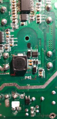
    I would also like to see a clear photo of the Step-Down converter itself. I want to analyze the circuit.
  • #76 18374248
    Matek920605
    Level 10  
    The diodes are all ok, I accidentally caught the wrong pin and that's why it showed me such voltage. However, I am not entirely sure if this viper22a is for sure working, i.e. it is definitely not working, because I checked the tension on it and accidentally shorted 2 legs together (hands shaking after New Year's Eve :D ) and the diode on the board started flashing and the sound intensified from the viper.
  • ADVERTISEMENT
  • #77 18374808
    ziro_9
    Level 10  
    Can you specify from the VIPer22AS datasheet which specific pins were shorted?

    As you say, it is possible that something shot in the control of the key. But there is also a risk that with a short circuit, the inverter released the overvoltage and burned the SG3525A and IR2110s. Flashing may be because downstream circuits are short-circuited and the inverter is resetting overload.
    Its amperage is only 100mA around and the ICs are unlikely to show any damage.

    The Zener diode D213 is responsible for determining the voltage of the converter. What's her symbol?

    I am enclosing a note below.
  • #78 18374862
    Matek920605
    Level 10  
    D213 is the symbol J1
    Pins 6-7 or 7-8 were shorted on viper22a, but I did not notice it in this area
  • #79 18375214
    ziro_9
    Level 10  
    The pins you entered are the drain pins and they are already internally short-circuited. A short circuit of either of them wouldn't affect anything.
    Maybe you misinterpreted which pin is the first pin. The first pin is the one next to the ST stamp.
  • #80 18375528
    Matek920605
    Level 10  
    Exactly, I thought the opposite was true, so it was pins 3-4 or 2-3.
  • #81 18375724
    ziro_9
    Level 10  
    Hmmm ... If only without starting the main power supply, just apply the voltage of the control systems supplied with the best laboratory power supply with the PROTECT function.

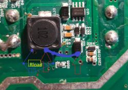
    At the beginning, set the voltage on it, e.g. 5V and the cut-off current of 300mA to 500mA. Apply the mass to the point behind the D215 diode, and the plus after the D214 diode. I have marked in the picture how to make the connection.

    And when the power supply would turn off due to overcurrent protection, it could mean that, for example, SG3525A or the drivers were blown.

    Check the D214 diode beforehand, because if it was punctured, it would constitute a short circuit in the circuit.

    Alternatively, you can use a power supply without this protection for the test and view the current with an ammeter plugged into the circuit.

    What do you think about it? Otherwise, to check the buck converter itself, you would have to disconnect the load from it.
    Edit:
    Of course, to the anodes of these diodes.
    Do you have the option to perform this test or look for other solutions? Because another solution is to desolder the SG3525A and IR2110s and then start the amplifier and it will come out whether the converter itself (Viper22a) will start or not.
    Or...

    If it weren't for SMD, the D214 diode's anode could be desoldered as well as the 102 foot of the coil. Both "pads" of both elements are on one output path (marked in the second photo). Short the soldered pins together in the air (with some wire) and add a balancing resistor to the ground of any value in the range from 300? to 1k?. This test will show more or less whether the converter itself is operational. The LED will not light because you will cut off the power to other systems. The voltage of the inverter will be put on the resistor and you only need to check if there is around 15V (on this resistor).

    And that I would be forgotten. You also need to connect the 220uF electrolytic capacitor at the output, so you can connect it in parallel with the resistor. Pay attention to the polarity.

    I would like to add that without an oscilloscope it will be difficult to go through the next stages ...
    T.amp TSA 4-1300 Power Amplifier Issue: Not Turning On, Red Diode Flashing, No Visible Damage
    T.amp TSA 4-1300 Power Amplifier Issue: Not Turning On, Red Diode Flashing, No Visible Damage
  • ADVERTISEMENT
  • #82 18376905
    INtRO_Tech
    Level 14  
    Hello,

    I would do this - throw out the SG3525 and both IR2110S and only then check the step down operation, it seems to be a faster method (this is how I mentioned SG and IR at home), you can easily do it with a pointed stock, unfortunately I lack the time and conditions for operation with this amplifier, but I also intend to sit down with it in the near future.

    The question is - when it is able to fire it, how to protect it from another failure hanging in the air. On the thoman website in the opinions (the bad ones) there are practically the same complaints about the whole TSA series in which this model excels.

    Regards
  • #83 18377415
    Michel424
    Level 14  
    I just don't know tsa4-700 is probably not so emergency ... it would be nice to do some repair manual, but for example I don't have an oscilloscope and I don't know whether to handle it unique. I have repaired some converters in car audio but here is a monster and everything in smd ech ... I'm afraid to take this tip ... because if the transistors would go by themselves, no problem, no problem, but the rest is a drama and that it has a common a board with power levels ... echo of defeat
  • #84 18377467
    INtRO_Tech
    Level 14  
    TSA 4-700 has a slightly different structure, i.e. the power supply and power stage boards are separate, only two IGBTs in the inverter and overall it is simpler, more repair-friendly, I have a Behringer iNuke 6000 and there is a great service, both schematic availability and readability plates, and the TSA 4-1300 is a massacre.

    I am waiting for an additional piece of this amp to compare the extent of the failure.

    I am thinking to desolder the transformer from the impulse and substitute the voltage on the secondary side from some smaller, ordinary transformer to see if it will even rise, the only question is what voltages are there, the analysis shows that there are definitely three different, symmetrical voltages:

    - the first to power preamplifier circuits, protect etc. (I suspect +/- 15-24V),
    - the second for the power amplifier (lower H-class), probably half of the maximum, i.e. +/- 90V symmetrical,
    - the third, also for the power amplifier (higher H-class), counting from the output power measured in Germany (2kW @ 4ohm), it may be around +/- 180V symmetrical.

    Regards
  • #85 18378061
    Matek920605
    Level 10  
    I changed the SG3525A again, the amplifier turned on, for 5 seconds and the IRGP burst: /
    The LEDs on the front panel lit up, followed by an explosion of transistors
  • #86 18378097
    INtRO_Tech
    Level 14  
    Hello,

    Welcome to the club, I had this stage in October too :)

    And did you check the power amplifier section itself, was there no shorted transistor that overloaded the converter? If everything was ok, then a further problem lies in the passive elements, the list of which is listed below:


    - R476 / R475 / R474 / R473 ---- 47 ohms,

    - D208 / D207 / D206 / D205 ----?

    - D750 / D751 / D752 / D753 ----?

    - R750 / R751 / R752 / R753 ---- 10kohm,

    - D215 ------?

    For me, 2 out of 4 IGBTs crashed, so I started to check the above-mentioned comparative method. these elements appeared to be damaged from measurements.

    After the bank explosion, you have smashed SG and IR (unless one branch survived).

    Further repair is rather an oscilloscope, now you would have to replace the SG, IRs and not insert the IGBTs, but only take the waveforms from their gate fields and compare, I suspect that, as in my case, there was a problem with the extinction of the IGBT and there was a short circuit by switching on another one, when the predecessor has not 'expired', and this is probably realized by passive elements on the board (please correct me if I think wrong).

    Unfortunately, due to the costs of the IGBTs themselves, this game is very expensive.
  • #87 18378190
    ziro_9
    Level 10  
    Oh yeah .... Such games are expensive.
    This is for the next time:
    You would need to know what signal goes to the gates, that is, before starting the entire amplifier, apply voltage to the control systems and see the waveforms with an oscilloscope.
    Perhaps some constant voltage appeared. When one IGBT shoots, it always entails at least a couple and control circuits.

    The fact that the inverter starts up does not mean that everything is fine at its level, first of all you need to check the "dead time", it cannot be too short. Because the IGBTs will be short-circuited for a certain moment.
    At the level of the signal coming out of the SG3525A, R478 is responsible for this.

    The first start-up can be carried out using a light bulb connected to the circuit, e.g. 100W.

    Fuses would also be useful on the rail in front of each channel, but unfortunately the manufacturer did not include in the design.

    The idea of powering the tip itself from an external source does not sound stupid, but the voltage issue ... From what I can see, the capacitors are for 80V, so I do not think that they are subjected to such a high voltage as 90V.

    When I get a power amplifier, I will try to desolder the impulse transformer and connect it to my Full-Bridge pickup.
    The voltages should be comparable when I choose the appropriate switching frequency.
    I have another switched-mode power supply with an adjustable cut-off current, on which I could try to place the amplifier. The voltage of this power supply is + -63V and + -126V and auxiliary + -18V and 12V.
    Maybe I won't be at full power, but at least I can make sure the handpiece is in working order.

    I will make a list of the items that have broken in my case.

    Did you have the original IGBT?
    On the example of another power supply, I once threw Chinese mosfets (I did not know, I did not break them that they were traveling. Bought on Allegro.) And they shot me after 6 seconds of normal operation.
  • #88 18378212
    INtRO_Tech
    Level 14  
    Hello,

    Yes, the IGBTs were original.

    At the end, I think it would be enough to substitute 2x40V (H-low) and 2x80V (H-hi), as for the preamp circuits, etc., here +/- 15V should also be good, you could actually see if the power ends would get up and, if necessary, avoid future less pleasant breakdowns after the inverter is repaired.

    Try to put a trafo on your reference full bridge device and measure its output voltages, as for the converter, I think it works around even 100kHz, next week I will talk to a friend who has a place for such fun, I will take the equipment with him along with devices and check what comes out of the SG3525 and what frequency, if it works, I will order 2x IR2110S and also solder, we will see what will appear on the IGBT gates.

    Regards
  • #89 18380143
    ziro_9
    Level 10  
    Hello,
    My further analysis of the circuit shows that the power amplifier works in the 3H class.

    -The 2506SF bridge rectifies the 1H voltage. (+ -40V?)
    - GBJ3006SF bridge rectifies 2H step voltage. (+ -60V?)
    -APT60DQ60BG diodes rectify 3H voltage. (+ -160V?)
    -Auxiliary voltages are rectified by SMD diodes. At least + -15V.
    As for the configuration of the capacitor connections, they are connected in series (I assume).

    I read it all from the photos posted in the subject.

    I will get this tip on Tuesday at the earliest and start working ...
    Regards.
  • #90 18380698
    INtRO_Tech
    Level 14  
    Hello,

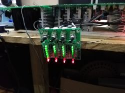
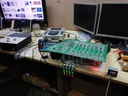
    Such a curiosity - I managed to fire this end under an alternative power supply, much lower, of course, it was about checking whether the power transistors, preamplifiers, etc. are functional and on the secondary side everything works.

    The tip spoke, the hero was a small 2x12V AC transformer, the impulse transformer was removed at the stage of measurements.

    I removed the CH2 block completely from the board because it had two terminal transistors punctured and a relay for this channel literally burned out.

    I started with the power supply, which supplies min. preamplifiers, connecting each symmetrical branch in turn, ending with H3.

    Ziro is right - this end is in the H-3, it has three power supplies, unless it is a typical H (H-2) and the next one after the auxiliary (the weakest) is also binding for the work of preamplifiers, accessories, etc.

    If I don't run out of time, I will organize a stronger 24V power supply and from some other amplifier I will connect a higher power supply to the power ends.

    ps. The faulty lights up because the amplifier had such a weak power supply that it did not have the strength to switch the relays, as long as the capacitors at the start kept this fault nicely extinguished :)

    Regards

    T.amp TSA 4-1300 Power Amplifier Issue: Not Turning On, Red Diode Flashing, No Visible Damage T.amp TSA 4-1300 Power Amplifier Issue: Not Turning On, Red Diode Flashing, No Visible Damage

Topic summary

The discussion revolves around issues with the T.amp TSA 4-1300 power amplifier, specifically its failure to turn on, indicated by a flashing red diode and no visible damage. Users share their experiences troubleshooting the amplifier, including checking the power supply, replacing damaged components like IGBTs, IR2110 drivers, and capacitors, and the challenges of finding schematics. The conversation highlights the importance of proper voltage levels, the need for fuses to prevent damage, and the potential for modifications to improve reliability. Several users report successful repairs after replacing critical components and adjusting the power supply configuration.
Summary generated by the language model.
ADVERTISEMENT