A warm welcome to you,
I'm trying to draw myself an installation diagram for a detached house to lay cables. And I am trying to do the best and easiest + with a back-up for the future, so that the installation can be extended if necessary.
The house is made of expanded concrete, also I already have grommets sunk in the walls, hence the desire to limit the amount of cables and WAGO, but I want it to be safe. For this I will want to do sonoffs or supla in boxes, so I am trying to fill some of them as little as possible with connectors.
Of course, the installation will be pluss-free.
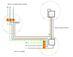
I'm thinking of something like this. In the diagram, two stair buttons, one 'lamp' and an outlet for more lamps on the same circuit (under separate switches). This way, I have a 3-wire cable going to the box from the switchboard, a 3-wire cable between the stairs and a 4-wire cable to the lamp in the ceiling (an extra wire with a phase, so that I can run the circuit further and possibly install some signal amplifiers there, a smart-home, speakers or who knows what else in a few years). Obviously 4-wire with a single light point, when there will be a lamp with the possibility of partially switching the lighting, then 5 wires will go.
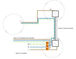
Does this have arms and legs, or is it better to connect the lamp more traditionally from the second staircase (i.e. I go there with a 4-wire cable: S1, S2, N, PE), and split the circuit in the first staircase (scheme 2)?
Of course, a variant of this scheme is still a 4-wire cable between the staircases - in general I think I should add PE there - for safety reasons in case of damage to the wires with a drill, for example. Although I'd rather run the cables as separate conductors anyway, so the chance of drilling goes down dramatically.
Suggestion:
.
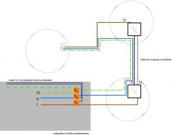
An alternative closer to tradition:
What about connecting the cables to further points in the circuit in the false ceiling? For me, this would be most convenient - few connections in boxes, fewer cables and more space for home controls
Pardon the makeshift diagrams


