logo elektroda
logo elektroda
X
logo elektroda

[YT] ESP32-S3-Relay-6CH six relays controller - schematic, flashing, Home Assistant

p.kaczmarek2 1431 9
ADVERTISEMENT
📢 Listen (AI):
  • Waveshare ESP32-S3-Relay-6CH relay module with six green terminal channels
    Waveshare ESP32-S3-Relay-6CH is an industrial-grade relay control module based on ESP32-S3 WiFi & BT module. It features RS485 connectivity, on-board USB to UART converter, six relays connected via PC817 optocouplers, a single WS2812B diode (for status display), onboard GPIO connector compatible with Raspberry Pi Pico Hats and can run on up to 36V thanks to the built-in XL1509-ADJE1 step down converter.

    Unboxing
    Let's see what's in the box. It seems that antenna and small screwdriver are included.
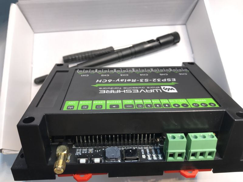
    Waveshare ESP32-S3-Relay-6CH controller with ports and connectors in a box
    The module is fully encased and all IO terminals are labeled. Relays are on the front side, each has three terminals (both normally open and closed):
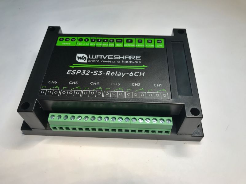
    Waveshare ESP32-S3-Relay-6CH relay module with six green terminal channels
    On the rear side, you have antenna connector, boot and reset buttons, buzzer, USB connector, RGB diode, status LEDs, power terminal and RS485.
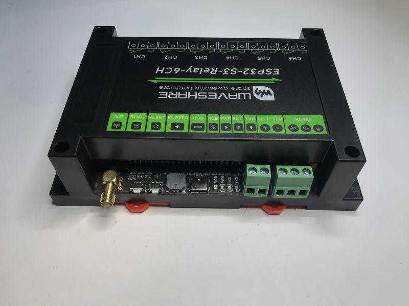
    WaveShare ESP32-3S-Relay-6CH controller with visible connectors and function labels

    Documentation
    Most of the information can be found on Waveshare wiki:
    https://www.waveshare.com/wiki/ESP32-S3-Relay-6CH
    Here is the board schematic - it shows which GPIOs are used for features like relays, WS2812 or which extra GPIOs are available inside.
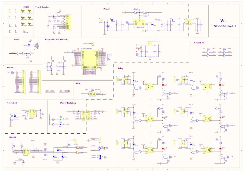
    Electronic schematic of ESP32-S3 module with interfaces, relays, and power supply
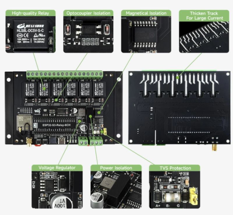
    ESP32-S3 relay board with 6 relays, isolation features and protection components shown
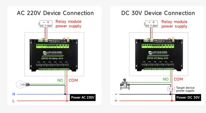
    Wiring diagram for ESP32 relay module with AC 220V and DC 30V devices
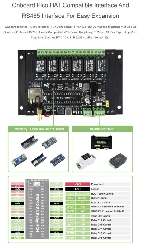
    ESP32-S3 board with RS485 interface and 40-pin Raspberry Pi Pico HAT header


    Quick teardown
    This is not needed for flashing and usage, but it's always interesting to check how things are made. You can unscrew the cover with the screwdriver that is included in the set.
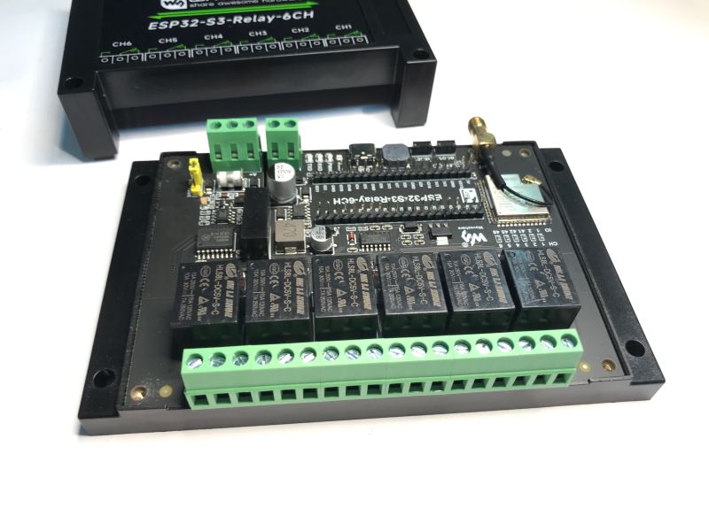
    ESP32-S3 module with 6 relays and green terminal blocks
    The device is made mostly out of surface mount components. There are two extra 2.54mm pin headers inside, which can be used to route out GPIO. They are compatible with Raspberry Pi Pico Hats.
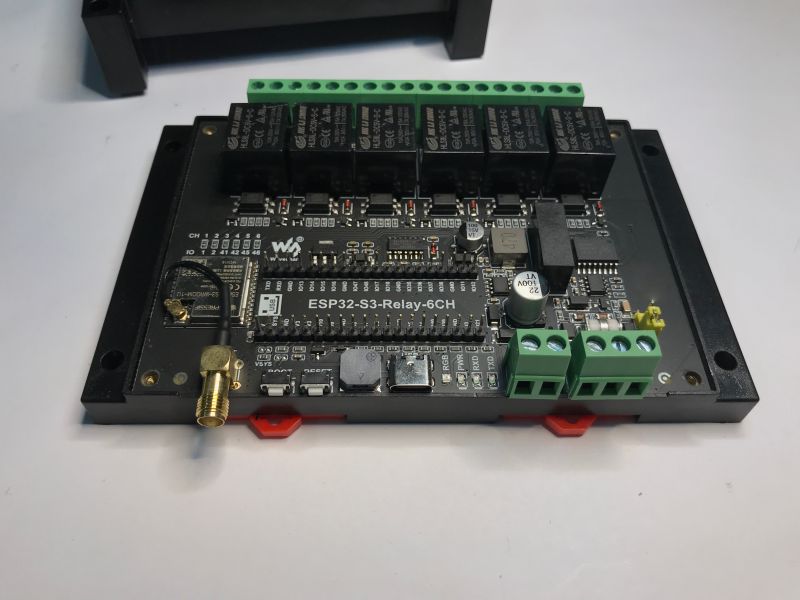
    ESP32-S3 board with relay module and green terminal connectors
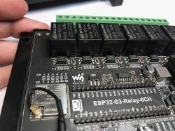
    Some closeups:
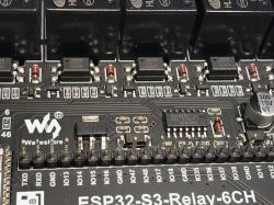
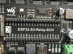
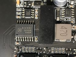
    ESP32-S3 board with six relays and screw connectors visible Close-up of ESP32-S3 relay board with relays, capacitors, and labeled pins Waveshare ESP32-S3-Relay-6CH board with labeled pins and electronic components Close-up of a circuit board with labeled IC and SMD components


    PlatformIO demo
    Device can be very easily programmed directly in PlatformIO. Here's a simple relay "hello world" that toggles a single relay in a loop:
    Code: C / C++
    Log in, to see the code


    The WS2812 is on GPIO38. It can be controlled either with a WS2812 library like FastLED or, for example, directly with RMT:
    https://www.elektroda.com/rtvforum/topic4115010.html
    There is also a Neopixel function that can work well with WS2812 as well:
    Code: C / C++
    Log in, to see the code

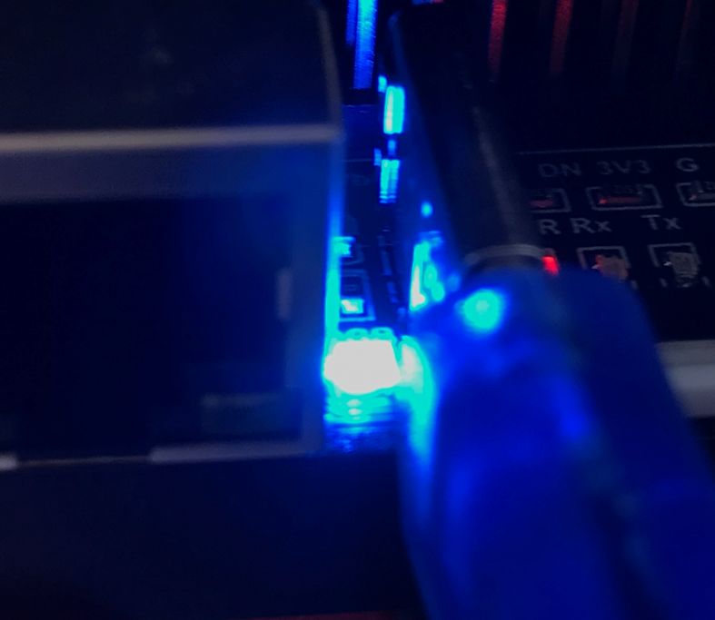
    Close-up of USB cable and blue LEDs on an electronic board with labeled connections
    NOTE: This particular photo is taken from the similar Waveshare board, but the one in the topic was tested as well.


    OpenESP32 demo
    OpenESP32 is a port of our OBK open source firmware. It runs on many chips from ESP family, including ESP32 S3. Flashing procedure and pairing with Home Assistant is shown here:


    I'm attaching flashing script:
    
    esptool.exe --port COM47 --baud 460800 write_flash 0x0 OpenESP32S3_1.18.156_4M.factory.bin
    

    Change COM port to suit your system.

    Template:
    Code: JSON
    Log in, to see the code


    The video does not cover it, but WS2812 can be also controlled in OpenESP. Just set pin role:
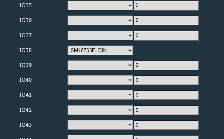
    Configuration interface with dropdowns and value fields for IO35–IO44
    and setup driver:
    
    startDriver SM16703P
    SM16703P_Init 1 GRB
    SM16703P_SetPixel 0 255 0 0
    SM16703P_Start
    startdriver pixelanim
    

    This way you can also get this to HA, but you must run HA discovery after running the script.
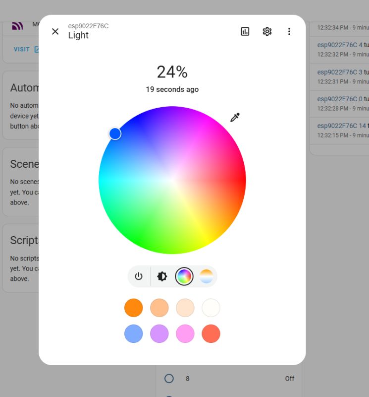
    Light control interface with color wheel and 24% brightness level


    Summary
    Waveshare ESP32-S3-Relay-6CH is a very easy to use module - you can either program it from yourself in PlatformIO, or flash a premade software like Tasmota - in this case I've presented our OpenESP32. This way you can easily pair it with Home Assistant and control and script relays, WS2812 LED also works well with our WS2812 driver. Futhermore, you can later script it in Berry language:
    Berry scripting for various IoT platforms - tutorial for OBK new script integration part 1
    Do you think that ESP32-S3-Relay-6CH module is a good idea for home automation and DIY projects, or would you prefer another one? Let us know!

    Cool? Ranking DIY
    Helpful post? Buy me a coffee.
    About Author
    p.kaczmarek2
    Moderator Smart Home
    Offline 
    p.kaczmarek2 wrote 13130 posts with rating 10913, helped 604 times. Been with us since 2014 year.
  • ADVERTISEMENT
  • #2 21688249
    krzbor
    Level 28  
    Perhaps someone knows - why do the Chinese, so renowned for their economy in electronics, use opto-isolation for relays? Even their cheap executive modules have opto-isolation.
  • ADVERTISEMENT
  • #3 21688875
    khoam
    Level 42  
    >>21688249 .

    Many Chinese modules are designed for universal use and a wide audience. The use of opto-isolation is a kind of standard, which guarantees that the module will be safe and work properly with different microcontrollers and in different environments, without risk of damage. This can be seen as a cheap Chinese insurance policy for the whole circuit 😀 .
  • #4 21689225
    krzbor
    Level 28  
    khoam wrote:
    This could be seen as a cheap Chinese insurance policy for the whole circuit
    .
    That's what I thought too, but the "secondary side" of the optoisolation is fed from the same voltage as the "primary".
  • #5 21690236
    khoam
    Level 42  
    krzbor wrote:
    I thought so too, but the "secondary side" of the optoisolation is powered from the same voltage as the "primary".
    .
    So what is the "Power Isolation" section on the schematic of this module used for?
  • ADVERTISEMENT
  • #6 21690279
    p.kaczmarek2
    Moderator Smart Home
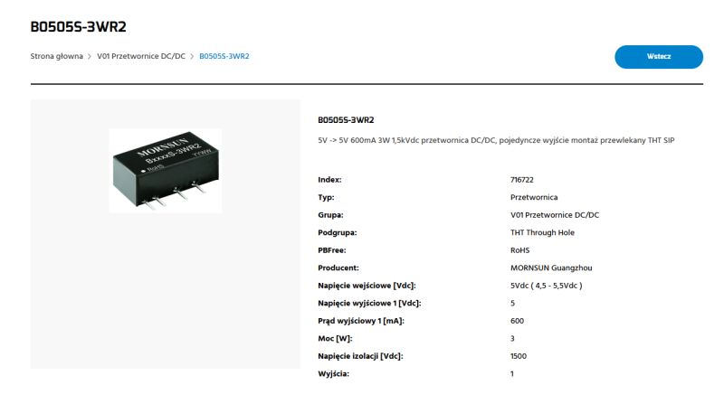
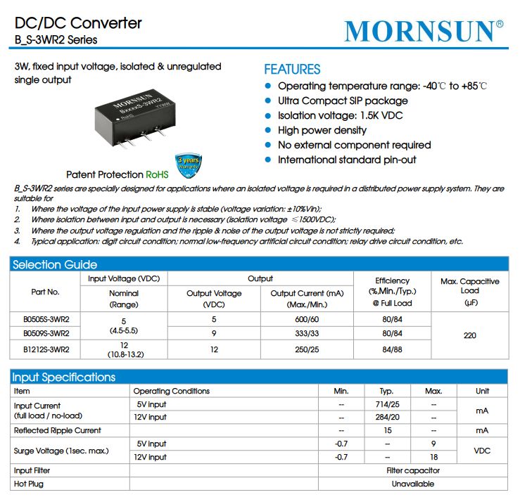
    @krzbor see the Power section and how the schematic is partitioned. There is a B0505S-3WR2 there and it powers a separate Relay-5V line while maintaining galvanic isolation.
    Mornsun B0505S-3WR2 DC/DC module in black SIP case with five metal pins. .
    Mornsun B0505S-3WR2 DC/DC converter datasheet with electrical specifications .
    Helpful post? Buy me a coffee.
  • #7 21690990
    krzbor
    Level 28  
    p.kaczmarek2 wrote:
    There is a B0505S-3WR2 and it feeds a separate Relay-5V line while maintaining galvanic isolation.
    .
    You're right - I hadn't noticed that. That is, to drive the relay from the I/O output of the processor we have: an isolated DC/DC converter, an amplifying transistor for the optocoupler diode, an optocoupler, an amplifying transistor for the relay coil and a fair handful of passive components. It looks as if someone does not believe that the relay itself provides galvanic isolation.
  • ADVERTISEMENT
  • #8 21691001
    khoam
    Level 42  
    >>21690990 .

    Redundancy is a form of safety. If one layer of isolation (e.g. the optocoupler) fails, the other (the inverter) can still provide isolation, with the final barrier being the relay itself. Such redundancy increases the reliability of the overall system and minimises the risk of cascading failures.

    The isolated DC/DC converter and optocoupler effectively suppress electrical interference that could pass from the high-current circuit to the sensitive digital circuit. Additional layers of insulation act as filters, preventing EMI interference from affecting the operation of the microprocessor.

    A complex circuit with an isolated DC/DC converter separates the ground circuits, eliminating the risk of ground loops. Ground loops are a common source of interference, especially in long-range systems or those connected to different power sources.

    All these things have been achieved at the relatively low price of the module and have been IMHO quite well thought out.
  • #9 21691035
    krzbor
    Level 28  
    khoam wrote:
    Redundancy is a form of security.

    I agree, but this is a uniquely non-Chinese approach. I was beginning to wonder if Chinese relays could be trusted. Note that the processor is not powered by 5V. There is an additional 3.3V stabiliser there with filter capacitors. I don't think there would be any interference problems here. Anyway, controlling a relay via the I/O of the processor with a transistor has been used successfully "for ages". I have even made such circuits myself. In addition, redundancy can lead to higher failure rates - the more components, the greater the risk of failure, especially as a DC/DC converter is not a simple circuit.
  • #10 21691039
    khoam
    Level 42  
    krzbor wrote:
    Additionally, redundancy can lead to higher failure rates
    .
    I would agree with this and it strongly depends on the quality of the components used.

    Maybe the designer of this module was thinking about scenarios that are statistically unlikely, but the consequences could be very serious. This approach is used for example in the military industry 🙃
📢 Listen (AI):

Topic summary

The discussion centers on the Waveshare ESP32-S3-Relay-6CH, an industrial relay control module featuring an ESP32-S3 WiFi & Bluetooth microcontroller. The module includes six relays isolated via PC817 optocouplers, RS485 communication, an onboard USB to UART converter, a WS2812B status LED, and a GPIO connector compatible with Raspberry Pi Pico Hats. It supports power input up to 36V through an integrated XL1509-ADJE1 step-down converter. The module is fully enclosed with labeled IO terminals, including normally open and normally closed relay contacts. Additional hardware features include an antenna connector, boot and reset buttons, a buzzer, USB interface, RGB diode, and status LEDs. A query was raised regarding the widespread use of opto-isolation in Chinese relay modules, even in low-cost designs, highlighting the emphasis on electrical isolation and reliability in relay control circuits.
Summary generated by the language model.
ADVERTISEMENT