logo elektroda
logo elektroda
X
logo elektroda

CozyLife B22 9W CW/WW LED Bulb - OpenLN882H Flash Conversion Overview [BP5758]

divadiow 192 15
ADVERTISEMENT
📢 Listen (AI):
  • Here's a swift tour of a basic CozyLife B22 9W CW/WW LED bulb bought from Ali Express
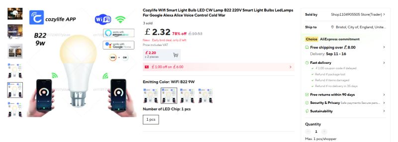
    Smart LED bulb B22 9W with app control and Wi-Fi connectivity
    https://www.aliexpress.com/item/1005009804894661.html

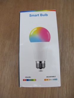
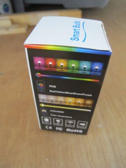
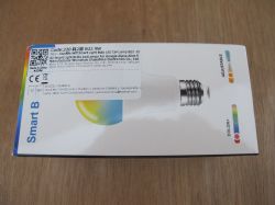
    The box gives the impression it's an RGB bulb, but it's just a generic box that's been seen with many varieties of bulb. This device is cold white/warm white.
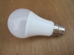
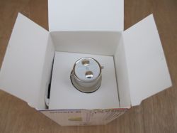
    White LED light bulb with bayonet cap lying on a wooden surface Open box with a GU10 bulb seen from above, showing metal connector pins. Smart Bulb package with RGB color and 2700–6500K adjustable white light Colorful Smart Bulb box showing RGB lighting and color temperature range
    Box of RGB WiFi LED smart bulb B22 9W compatible with Google Alexa

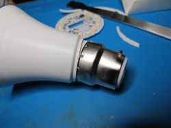
    No markings on the exterior of the bulb at all. With reasonable force the dome can be popped off by hand, the silicon removed with a spudger and the positive/neutral lugs at the base lifted out with a scalpel.
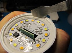
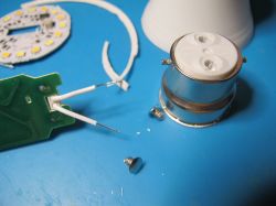
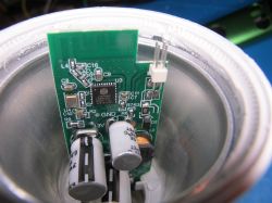
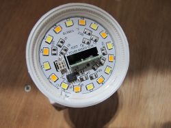
    Close-up of LED lamp interior with circuit board and multiple LED elements Disassembled LED bulb showing internal electronics and mounting components


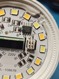
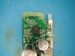
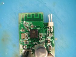
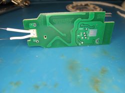
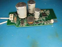
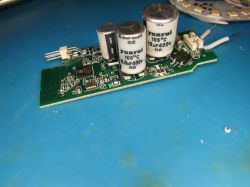
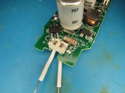
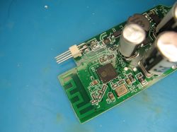
    Close-up of LED circuit board with SMD LEDs and BP5758 IC Close-up of green PCB with microcontroller, capacitors, and a PCB antenna. Close-up of green PCB with LIGHTNING LNB82HK1 chip and SMD components Green circuit board with visible traces and two connected white wires on a blue surface Close-up of circuit board with capacitors, inductor, and integrated circuits Electronic circuit board with electrolytic capacitors and SMD components Close-up of PCB with capacitors, resistor, and MB10F bridge rectifier Printed circuit board with capacitors, a chip, and an integrated PCB antenna Disassembled LED bulb with metal base and internal parts on blue background Close-up of PCB with electronic components inside an LED lamp housing Close-up of an LED bulb's internal circuit board with LEDs and components.

    A9, RX, TX, GND and 3V3 are nicely labelled on the rear of PCB
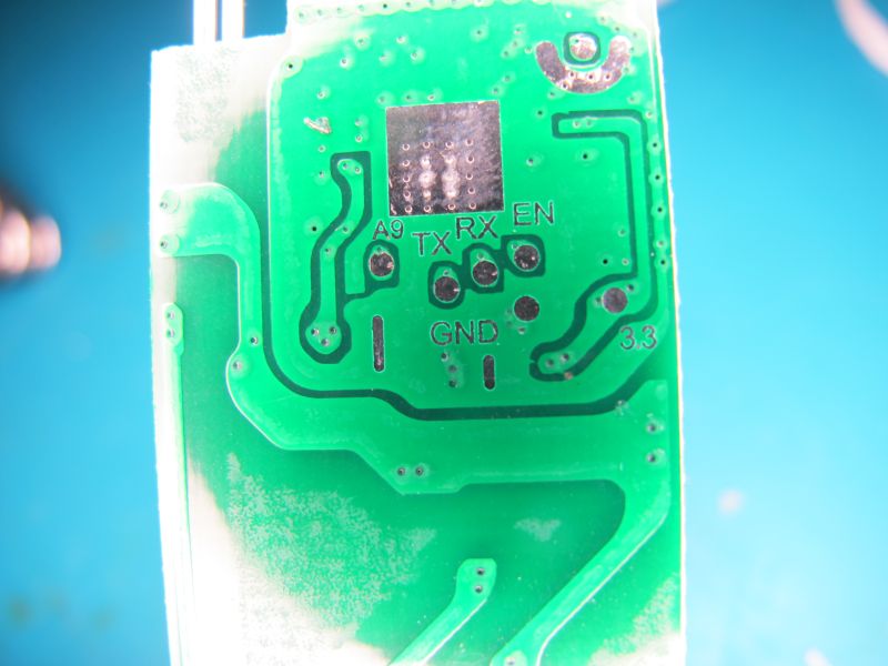
    Close-up of green circuit board with labels TX, RX, GND, and 3.3

    soldered-up ready for flash backup and programming of OpenLN882H
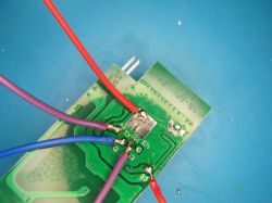
    PCB with soldered wires in various colors on a blue surface

    boot log from TX at 2000000 baud
    Code: Text
    Log in, to see the code


    A9 grounded for UART download mode, Easy Flasher takes backup
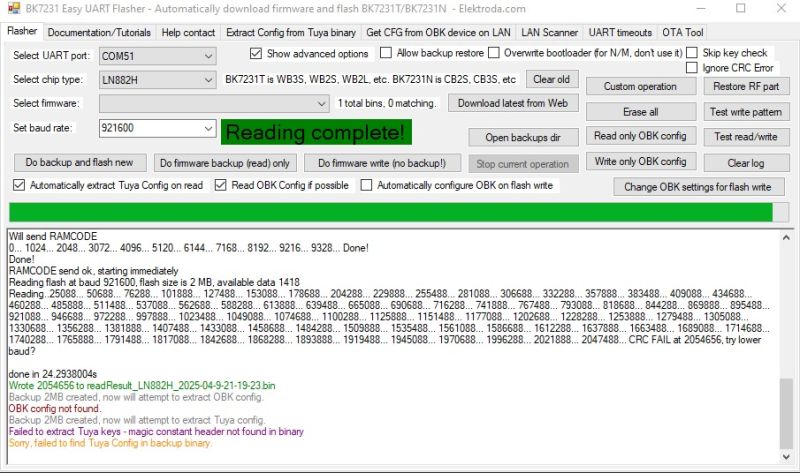
    BK7231 Easy UART Flasher interface with Reading complete! message

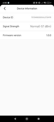
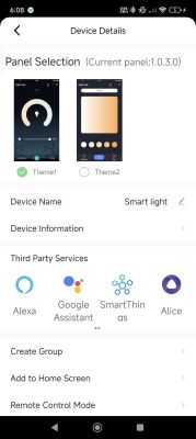
    backup flashed to dev board to be sure it was a good backup. It boots and can be paired with CozyLife app
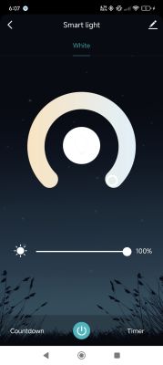
    Smart lighting app screen set to white mode with brightness at 100%. Settings screen showing device ID, signal strength, and firmware version Smart light app screen with control panel theme selection and integrations

    A9 still grounded Easy Flasher programs OpenLN882H to flash
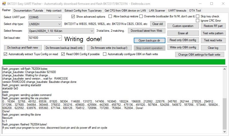
    BK7231 Easy UART Flasher interface showing successful firmware flashing log

    OBK boots, AP broadcast, accessed at 192.168.4.1 when connected as a client, join home wifi.

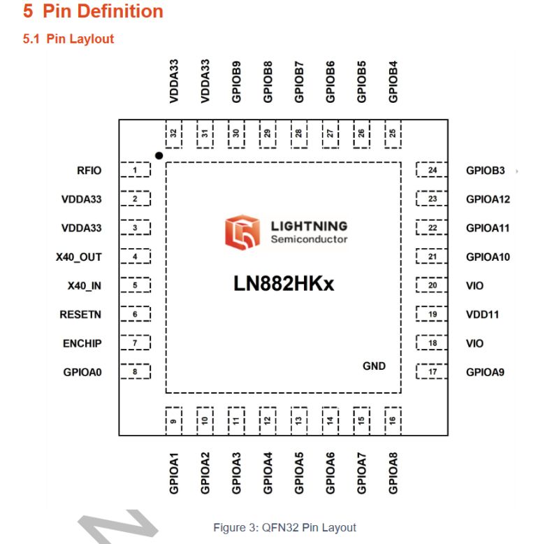
    We see in a close-up picture that A5 and A6 are tracing to the 4 pins that go to the LED disc. These two will be CLK and DAT lines for the BP5758 controller chip on the disc.
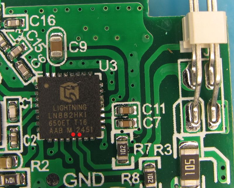
    Close-up of LIGHTNING LN882HKI chip on green PCB with SMD components

    Pin layout diagram of LN882HKx chip in a QFN32 package

    A5 = BP5758D_DAT
    A6 = BP5758D_CLK

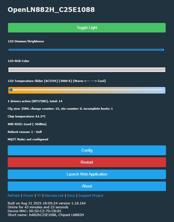
    LED control panel interface with brightness and color temperature sliders

    startup command to limit current and temperature
    Code: Text
    Log in, to see the code


    More detailed LN882H info and guides:
    https://www.elektroda.com/rtvforum/topic4027545.html
    https://www.elektroda.com/rtvforum/topic4085019.html
    https://www.elektroda.com/rtvforum/topic4028087.html
    https://www.elektroda.com/rtvforum/topic4032240.html
    https://www.elektroda.com/rtvforum/topic4050274.html

    search device list for other examples; https://openbekeniot.github.io/webapp/devicesList.html


    OBK template
    Code: JSON
    Log in, to see the code


    Flash backup: https://github.com/openshwprojects/FlashDumps...mits/a8a1da6260ef37a73fc6be03a2544df571b6251c

    Cool? Ranking DIY
    About Author
    divadiow
    Level 35  
    Offline 
    divadiow wrote 3478 posts with rating 605, helped 299 times. Live in city Bristol. Been with us since 2023 year.
  • ADVERTISEMENT
  • #2 21653834
    p.kaczmarek2
    Moderator Smart Home
    CW bulb with 5-channels two-wire chip BP5758? So 3 out of 5 channels are not used... How does it make sense?

    Is it at least cheaper than RGB+CW?

    With the current board layout, you could easily solder Red, Green and Blue LEDs and get back it working into RGB+CW mode.
    Or wait - maybe not, depending on the power supply circuit? That powers LEDs?

    How much did they even save by stripping four red, green and blue diodes? Considering they came extra cheap and in packs of 100 or 1000 or so on...

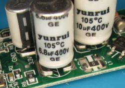
    Also, that's indeed an interesting way to mount a capacitor:
    Close-up of Yunrui electrolytic capacitors on a PCB

    Very interesting. I am happy to see you still making teardowns, especially that even now they feel fresh and show new things.

    PS: Maybe it would be economically viable to set lower current for those diodes, depending on how bright you need them. This can seriously prolong their life, some people even do the same for non-smart bulbs:


    Helpful post? Buy me a coffee.
  • ADVERTISEMENT
  • #3 21653839
    divadiow
    Level 35  
    p.kaczmarek2 wrote:
    CW bulb with 5-channels two-wire chip BP5758? How does it make sense?

    ha. yeh, dunno. it does mean the RGB picker on OBK GUI is a little bit redundant.
  • ADVERTISEMENT
  • #4 21654132
    p.kaczmarek2
    Moderator Smart Home
    I see, I guess we need some kind of method to mark in LED_Map that RGB channels are not used...

    I haven't seen yet any other device that had 5-channel I2C-like LED controller but used only two channels.
    Helpful post? Buy me a coffee.
  • #5 21654145
    divadiow
    Level 35  
    p.kaczmarek2 wrote:
    I haven't seen yet any other device that had 5-channel I2C-like LED controller but used only two channels.

    hmm yes. I just scanned device list for BP5758 and each device mentions RGB in some form. seems to be the first.
  • #6 21654153
    insmod
    Level 27  
    I have a 6W E27 CB2L BP5758D RGBWW without CW, so 4 channels.
    Plus i remember i saw E27 CB2L BP5758D without RGB on some russian site.
    I can find it if you're interested.
  • #9 21654246
    p.kaczmarek2
    Moderator Smart Home
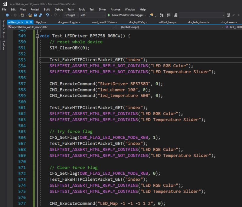
    I am preparing self test to add handling for these cases.
    Test code for LED driver shown in Visual Studio interface
    I will probably opt for something like this:
    
    LED_Map -1 -1 -1 1 2
    

    This means that only OBK C and W are mapped to channel 1 and 2 of BP5758, and others are 0, and page code checks for that and concludes it's CW.

    Any suggestions, before I implement it?
    Helpful post? Buy me a coffee.
  • #10 21654269
    divadiow
    Level 35  
    not from me!

    -1 -1 -1 make sense to me

    Added after 2 [minutes]:

    does that also cover @insmod's missing CW

    Code: Text
    Log in, to see the code
  • #11 21654339
    p.kaczmarek2
    Moderator Smart Home
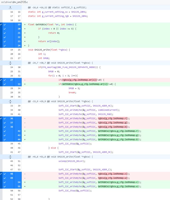
    The only downside is that I need to check for this -1 (0xff, 255) in remap... hopefully this will suffice:
    Screenshot showing a code diff in the C file highlighting the use of GetRGBCW
    I will open a PR in few minutes.

    Added after 26 [minutes]:

    https://github.com/openshwprojects/OpenBK7231T_App/pull/1789
    Helpful post? Buy me a coffee.
  • ADVERTISEMENT
  • #12 21654391
    divadiow
    Level 35  
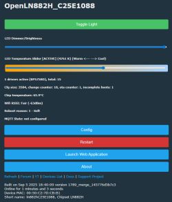
    GUI looks good but sadly no light. toggling dimmer makes no diff

    LED control panel interface with brightness and color temperature sliders

    Added after 1 [minutes]:

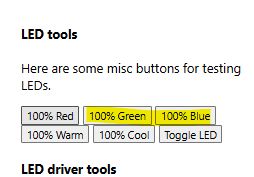
    toggling 100% green and blue buttons does bring the CW/WW LEDs on

    Highlighted “100% Green” and “100% Blue” buttons in the LED tools section

    Added after 30 [seconds]:

    startup

    Code: Text
    Log in, to see the code
  • #13 21654419
    p.kaczmarek2
    Moderator Smart Home
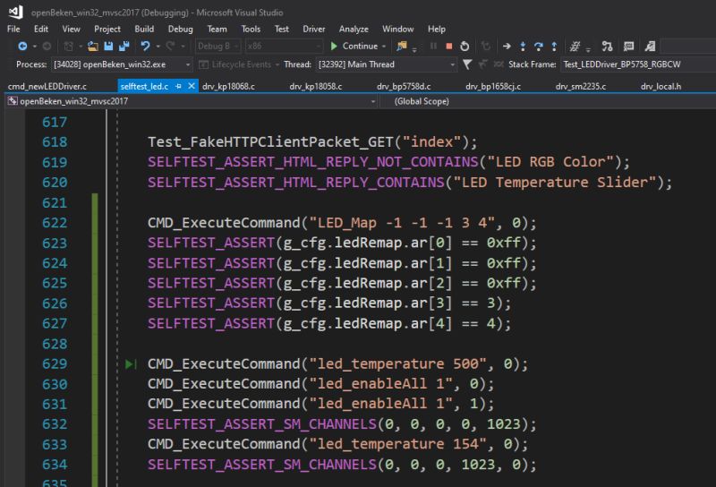
    I suspect I know what may be wrong. If you have CW light, then OBK CW channels have indexes 3 and 4. So your LED_Map should consist only of -1 (for skipped channels) and 3 and 4.

    Added after 2 [minutes]:

    In other words, this self test passes:
    Autotest code in Visual Studio showing LED_Map configuration and SELFTEST_ASSERT checks
    Helpful post? Buy me a coffee.
  • #14 21654440
    divadiow
    Level 35  
    p.kaczmarek2 wrote:
    So your LED_Map should consist only of -1 (for skipped channels) and 3 and 4.


    yep. that's all it was. dimmer, toggle, web app all good now

    Code: Text
    Log in, to see the code


    Added after 6 [minutes]:

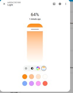
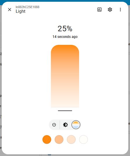
    HA works. RGB bits are there but CW/WW works

    Light control app interface with brightness set to 64%
  • #15 21654457
    p.kaczmarek2
    Moderator Smart Home
    I didn't adjust HA discovery yet, so that's expected. I only changed UI of OBK.

    Added after 4 [minutes]:

    Pushed HA Discovery. I just count number of non-negative remaps and use it as number of pwms. Didn't test it yet. I may cover it with self tests soon.
    Helpful post? Buy me a coffee.
📢 Listen (AI):
ADVERTISEMENT