Dear toto and that's why I never got interested in it. If ESP82XX is there it will definitely work on Tasmota. By the way, I recommend a cheaper alternative of 3 pzem-004 v3.0 and Tasmota
Yes, there is no wi-fi. The module itself communicates via UART with ESP8266. It may even be ESP-01 I recommend version 3.0 because it works well on LVTTL and has flashing LEDs where you can immediately see if there is communication. Previous versions had to be slightly modified. So change the resistors on optocouplers. In addition, version 3.0 shows the frequency of the network. It is connected simply: rx-tx tx-rx mass and 3.3V power supply. With more PZEM-004 connected to one UART, you need to give the BAT45 diodes according to the diagram somewhere on the github. When I find it.
The basic configuration is to paste the following line into the template configuration: For version 3.0 it will be: {"NAME": "HW-655 PZEM", "GPIO": [0.62.0.98.0.0.0.0.0.0.0.0.0], "FLAG": 0, "BASE": 1} Or manual selection in the configuration of the generic module in Tasmota.
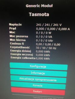
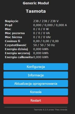
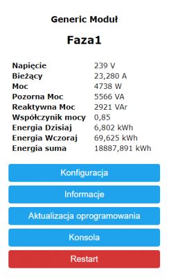
Thanks to PZEM-004T we get readings: Voltage, current, active, reactive, apparent power and cos phi. In addition, it counts the kilowatt hours today and total. After mqtt we send ourselves wherever we want.
How would I help you.
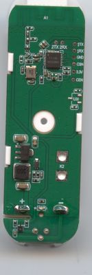
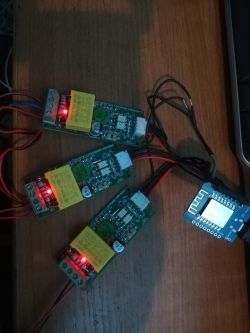
This is what it looks like. It's an older version that doesn't show the frequency.
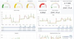
Yes, that's this drawing. When the connection of many on one UART was just beginning and there were problems, I did on three separate ESP-01. It works fine now. But ESP-01 are cheap so I got used to it and I still do. Of important things, for the readings to be correct, the PZEM power supply must be from the same phase on which the current transformer is placed. Otherwise the indications of power and cos phi are incorrect. Obvious obviousness, but I was deeply surprised to see cos phi at 0.2. And this is an example of data sent to Influxdb and displayed in Grafana:
Ok, to be precise, the PZEM-004 has two power supplies. One main via AC terminals which also measures voltage and phase shift angle. The second power supply is a low-voltage power supply only for optoisolation systems. By making three plays side by side, we have to supply each piece from a different phase. Then we put the current transformer on the same phase as it is connected to the AC terminal. From the low voltage side, it does not matter, because it only supplies optocouplers. I power them from a common 3.3V power supply from which I power all PZEMs and ESP8266.
Erbit wrote:
What are you measured that the current consumption is over 9kW
It's still a low consumption. I can't say exactly what. It is a type of agricultural activity.
Also remember to connect three PZEM-004 to one UART, you must first connect each one separately and set each other address. Only when each of them has its own address can they be fastened together.
Speaking of energy meters, I will boast of today's night fight with three DGM PP-W162, which is commonly called "Measurement socket from Biedronka".
First of all, the socket has a very nice compact housing and, in addition, it can be bought for about PLN 40 or less. Unfortunately, the same, cool compact housing is a curse because even though disassembling the glued housing of the socket is not a problem, getting to the ESP pins is a challenge.
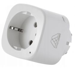
The socket looks like this:
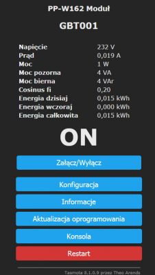
Here are the effects on Tasmota:
Interestingly, the visible values are the idle work of two Sonoff POWs, which I connected to the socket for testing.
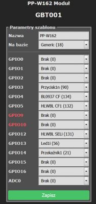
And this is the configuration.
Due to its compact housing, the socket perfectly replaces the clunky Sonnoff POW in many places.
Thank you very much, colleague @yszne for giving me the right direction. I ordered it, it came, it was delayed (coronavirus), today I put it together in a spider's web, the effects below.
Probably there will be assembly over the weekend.
I would also like to thank my colleague for "giving direction" with tasmotas in another topic. Today, a few devices with tape measure are already functioning, and they are fully (bidirectionally) integrated with home automation. The 3F counter will also be so integrated.
2) As my colleague @xury noticed above, the process of addressing the module must take place on only one connected PZM004. From myself I will add that probably the "ModuleAddress 2" command works on the voltage connected to PZM004 from the measurement side (230V!). Without this connection, I was unable to save the module address, even though Tasmota was saying "OK" after each addressing.
3) The template used on the blog caused the tasmota to be reset to factory settings from time to time. I used my own template.
4) Tasmota has a specific error in the algorithm looking for PZM004 addresses. Every time it starts, it starts by default all 3 addresses (1,2,3) and starts searching. If it does not find all 3, then whatever is missing it sets reading from addresses 1,2 and tries to read again. If it doesn't find either of the two (no matter which one!), It sets address 1. As a result of such a wrong search algorithm, if Tasmota does not find address 1, it will not connect to any! For this reason, in many descriptions you can find information to first put the voltage on the PZM004 and then start Tasmota.
Hello colleagues, I am connecting to the thread because I am looking for a 3f meter with a function that distinguishes between energy fed into the grid and consumed energy. Zamel MEW supposedly meets this, but is quite expensive. I am looking for a ready-made solution that will fit in the board in place of 3 phase control bulbs. It is best if it is already in a suitable housing for installation in a switchboard.
I don't think that with such requirements you will find anything other than Zamel MEW. Besides, even if you don't count on paying half as much as for Zamel MEW. I was assembling with 3 * pzem-004, Wemos, some cables, external antenna, without housing and not fitting the rail, I "paid" less than PLN 200 and I had to put it all together and program it myself.
It will find, but it will not be cheap: SHELLY 3EM.
maybe you can help me - I installed a meter for the heat pump - Zamel LEM-40. of course, according to the instructions - an electrician did it. after the first day, nothing has changed on the numerator - it was 0.09 and it is still so. The PC was working during the day and heated the water in the boiler. what caught my eye is the LEDs L1 and L2 under the display and 1000 imp / kWh, and L3 is off. Does this mean that the meter is defective?
The price does not scare me, but I would like to have everything integrated uniformly in my HA, not in someone else's clouds.
Besides - I want to track more than one connection and one load to visualize energy flows nicely (and then the division into apartments)
So, questions for the more experienced: 1) My guess is that this PZEM-004 v3 does not have the ability to energy energy in two directions? Because looking briefly at the communication protocol - I do not see this parameter (energy direction) anywhere - but maybe I am wrong?
2) If not PZEM, what else could be integrated with ESP / ESP32 to measure 1 or 3 phases in two directions?
3) Is there any soft alternative for this MEW-01? 4) Do I only have ShellyPM3?
I use MEW-01 in HA via Supli server, but from what I remember, when configuring MEW01 it was possible to choose the operating mode, either by Supli server, or without Supli server after MQTT.
I haven't tested so I can't write if and how it works without Supli server.
And it works beautifully locally. I've had it installed for about two weeks. Measurements are in line with the PGE meter. It integrates very nicely with HA. You practically do not need to do anything.
Gentlemen, I put it on NodeMcu and Tasmota - the older version 8.2.0 because I saw that in your higher posts it works like that. And it also works:
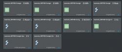
I have integrated with Domoticz via Autodiscovery of Tasmota Devices and no voltage indications only power indications:
What is wrong ? I also tried version 10.0 and also the same. If I give IDX in the Domoticz settings in Tasmota, the voltage will fly, but only there is a loss in these settings for one phase.
With Domoticz it is rather through Nodered and MQTT. Domoticz's service in Tasmota comes down to a few basic things. It is not Tasmota's fault, but only meager support for MQTT in Domoticz.
Write something more about this Nodered because I do not know the topic at all, is it some domoticza plug or something ??
Failure, I wanted to monitor my tensions, and here is such a lame. I think that 3 x ESP8266 will be assembled and one PZEM will then send voltage to each one, but again it will not add up the energy used.