logo elektroda
logo elektroda
X
logo elektroda

Vidos ZS42 Code Lock Setup: NC Bolt Connection Issue

zen44ek 4194 26
ADVERTISEMENT
Treść została przetłumaczona polish » english Zobacz oryginalną wersję tematu
  • #1 18865911
    zen44ek
    Level 10  
    I bought a code lock for a vidos zs42 wicket. I have connected everything according to the diagram, programmed the pin, however the lock does not release.

    Link to instructions and diagram.
    https://vidos.pl/wideodomofony/kontrola-dostepu/zs42-zamek-szyfrowy/
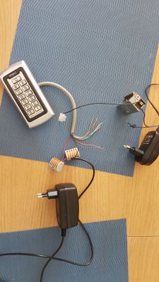
    I have the deadbolt to + on one power supply. Then the blue cable from the lock to the deadbolt, the black cable from the lock to the - from the 2nd power supply and the red cable from the lock to the + from the 2nd power supply. Is this lock definitely working with the nc bolt? After entering the pin nothing happens.
  • ADVERTISEMENT
  • #2 18866035
    ta_tar
    Level 41  
    Firstly, draw as you can what you have connected where. Secondly. Have you programmed the PIN correctly. When you enter the code and confirm with the # sign, does the colour of the LED change to green? And thirdly. What is your set time for opening the deadbolt?
  • ADVERTISEMENT
  • #3 18866280
    zen44ek
    Level 10  
    The LED lights up green when the pin is entered. I didn't change the timing, I think it's 4s as standard.
    Vidos ZS42 Code Lock Setup: NC Bolt Connection Issue .
  • #4 18866317
    ta_tar
    Level 41  
    Why are you using two power supplies? Don't you have one powerful power supply? Where do you connect the second wire from the top power supply(photo)?
  • #5 18866365
    zen44ek
    Level 10  
    I don't join, I use two because of the note in the instructions. No m diode.

    If you use the same power supply for a deadbolt and a keypad, protect the
    The device must be protected against surges by means of a rectifying diode with the correct
    polarity.
  • #6 18866374
    ta_tar
    Level 41  
    zen44ek wrote:
    I do not attach, I use two for the reasons noted in the instructions. No m diode.
    This is how you want to get voltage on the deadbolt if you have the plus connected from the power supply and the minus in the air? There is nothing coming out of that power supply that powers the lock to the deadbolt.
  • #7 18866390
    zen44ek
    Level 10  
    Nothing direct. How do I do it then?
  • Helpful post
    #8 18866456
    ta_tar
    Level 41  
    Connect the other end of the power supply (the one from which the first end goes to the deadbolt) to the purple one, as long as this power supply is strong enough (has sufficient current) to activate the deadbolt.
  • #9 18866494
    zen44ek
    Level 10  
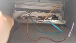
    Thank you, it works. I am now wondering how to connect this to the wicket where the intercom is and there was a deadbolt before, which I dismantled, the + and - cables from the intercom stick out. Do I do it on the one power supply that is already there, or do I somehow connect a 2nd power supply.
    Vidos ZS42 Code Lock Setup: NC Bolt Connection Issue Vidos ZS42 Code Lock Setup: NC Bolt Connection Issue .
  • #10 18866676
    ta_tar
    Level 41  
    Without knowing the entire layout of the intercom, I cannot remotely put this together. If you've had problems with such a simple matter as connecting a simple code lock, then to put two different circuits together you'll probably have to call someone locally.
  • ADVERTISEMENT
  • #11 18866710
    zen44ek
    Level 10  
    I've wired it all up to this one power supply, the opening from the intercom and the lock works. The problem is that when I have the power supply connected to the intercom and the combination lock, there is a noise from the intercom speaker. What could be the cause?
  • #12 18866717
    ta_tar
    Level 41  
    On the table you were afraid to connect to one power supply because you didn't have a diode and here you have connected as many as three devices and also without a diode? Unplug the power supply to the combination lock and see if it stops.
  • #13 18866757
    zen44ek
    Level 10  
    It stops when I disconnect the power supply to the lock.
  • #14 18866762
    ta_tar
    Level 41  
    And have you checked that this power supply has an output for 12 volts AC (alternating)? The question is whether the lock is still operable.
  • #15 18866808
    zen44ek
    Level 10  
    It still works on the previous circuit so I guess it's working. I don't think I can figure it out on my own, I thought I had a 230v connection to the intercom so I could probably figure it out. I'll call an installer in that case. May I know the cause of the crackling noise from the speaker?
  • #16 18866875
    ta_tar
    Level 41  
    Your power supply is on AC, you are connecting a device that needs DC, it is difficult to tell from a distance, but the cause is probably in the mismatch between the devices and the different power supplies to them.
  • #18 18867426
    zen44ek
    Level 10  
    From my power supply comes out 0-red, white AND 12v-red, green. Two cables each. I carefully connected them under the lock, red from the cipher under red and green (12v), black from the cipher under red and white (0). Then the speaker made a rustling sound. I don't get 230v to the wicket, if I did I'd put in a power supply and that's it.
  • ADVERTISEMENT
  • #19 18867438
    Ircys
    Intercoms specialist
    Let's try to sort out the chaos you are introducing.
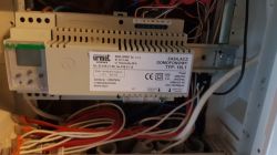
    1) You have an intercom system with an Urmet 18L1 PBX.
    You want to add a Vidos zs42 keypad to it and you don't have anything to supply it with
    or so ?
  • #20 18867447
    ta_tar
    Level 41  
    zen44ek wrote:
    There is no 230v to my wicket, if there was I would give a power supply and it would be done.

    The author's problem is that there is no 230 v supply at the wicket.
    See if you don't have a spare pair of wires to pull up 12 DC to power the keypad from where you have 230 V.
    Maybe the author knows something about electronics and could use some sort of rectifier bridge but we don't know its capabilities.
  • #21 18867499
    zen44ek
    Level 10  
    I'm not some kind of expert but I always try to do something myself first. Even though it doesn't work out I learn something. I have only cables from the Urmet 18L1 power supply to the wicket, the ones in the photo: 0, 12, G, MP, SU, MU, GP. There are two cables going from each.
  • #22 18867522
    ta_tar
    Level 41  
    zen44ek wrote:
    There are two cables going from each.
    Am I to understand that there are two cables going to each point? Then why don't you take out some free pair, e.g. one from GP and one from MP, and make a free pair. And with this free pair you can power the cipher from an additional power supply (remember, check the colours to make sure you have disconnected the same wires on one side and on the other).
  • #23 18867538
    zen44ek
    Level 10  
    Good idea, that's what I'll do albeit I'm afraid not two free pairs. I'll see tomorrow.
  • #24 18867546
    Ircys
    Intercoms specialist
    You can also calmly give a small rectifier bridge and power the keypad from the intercom power supply.
  • #25 18867573
    ta_tar
    Level 41  
    zen44ek wrote:
    Good idea, yes I will do that although I'm afraid not two spare pairs. I'll see tomorrow.
    Simply enough if you can spare one pair to power the cipher.
  • #26 18867600
    zen44ek
    Level 10  
    ta_tar wrote:
    zen44ek wrote:
    Good idea, yes I will do that although I'm afraid not two spare pairs. I'll see tomorrow.
    Surely enough if you can spare one pair to power the cipher.
    .

    Why are there pairs of cables going? Can I therefore take from 12v and from N? What kind of power supply will I need, the kind that I put myself in the switchboard, can you suggest?

    Added after 11 [hours] 18 [minutes]: .

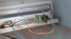
    At the wicket I still have such a board into which 0,mp, GP enters. So can I use one of the mp and one of the GP? There is nothing free.
    Vidos ZS42 Code Lock Setup: NC Bolt Connection Issue .
  • #27 18868286
    ta_tar
    Level 41  
    zen44ek wrote:
    I can therefore use one of the mp and one of the GP
    And what did I suggest to you earlier?(#22)

Topic summary

The discussion revolves around the setup of a Vidos ZS42 code lock, specifically addressing issues with connecting the lock to a deadbolt using two power supplies. The user initially faced problems with the lock not releasing after programming the PIN, despite the LED indicating successful input. Responses highlighted the importance of proper wiring, suggesting that the deadbolt must be correctly powered and that using two power supplies may complicate the setup. A solution was provided to connect the power supply correctly to the deadbolt, which resolved the initial issue. Further complications arose when integrating the lock with an intercom system, leading to noise issues from the intercom speaker. Participants advised on potential wiring solutions and the need for a rectifier bridge to ensure compatibility between AC and DC power supplies.
Summary generated by the language model.
ADVERTISEMENT