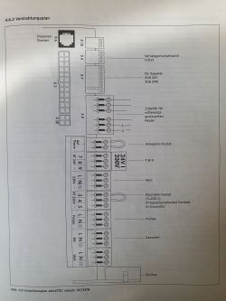
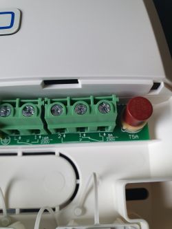
Hello, I am looking for information on how to connect the above mentioned cooker to the Homematic system.
The current controller is a vrc410 connected to sockets 7-8-9 (24V), however this one is defective (it heats only on "Full"), moreover, I want to make a separate control for each room + additionally I have underfloor heating in a part of the flat, therefore the circulating pump comes into play, which also has to be controlled in a different way than "manually" (I bought the flat in such a state, I do not know who made the current system).
From all the information I have read elsewhere, I understand that the vrc410 in such a constellation has to be on full for this to work, however, you have to block the heating in the furnace in some other way as the Homematic thermostats will give the signal that heating is not needed.
And here is my question, the furnace has an output still on 230V (3-4-5, 3 and 4 are bridged normally) and according to the diagram I see that 3 is 230V, 4 Control, 5 Neutral/0
According to the diagram in the HmIP-WHS2 manual:
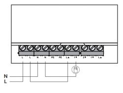 .
.
So here, as I see it, you need to connect the 230V supply from the outside to the L and N on the left, then you take the "section 1" (the first block of 2 sockets on the right from the PE ground):
- L with the up arrow goes to the second L in the block quite on the left
- 1 with the down arrow to input 4 on the cooker (Control)
- output 5 on the furnace goes to the second N on the left
- output 3 on the cooker remains vacant
That is, when the HmIP-WHS2 gives the "Heat" signal, it closes the circuit and current flows from the outside, via L with arrow up, 1 with arrow down, to the furnace on port 4 and from the furnace port 5 to Neutral on the "outside" (roughly speaking, but you know what I mean, I know it's variable)
Up to this point understandable, the doubts start however if I want to connect a pump to the second channel:
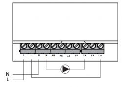 .
.
We already have L2 and N2 draped (to the left of the Earthing) and would now need in "Section 2" quite to the right:
- from L2 to L with an upward arrow
- 2 with down arrow to L from Pump
- N from pump to N2
In this case, won't there be a conflict/short-circuit somewhere if, for example, only the Pump or only the Stove is switched on ?
Generally, if the cooker is on and the heating is to go to underfloor heating, the pump must be on, but it does not have to be on if it is going to "normal" radiators (because then the internal pump from the cooker works), at the same time there is a possibility that only the floor pump will be on (because the cooker has finished heating, but we want the circuit to continue, or even in a situation where we want the cold water circuit to work).
At present, there is no other way to control the cooker; if I had a newer one, I would connect via eBus to another thermostat and control via IFTTT when the heating of the cooker should be switched on.
Any suggestions welcome
The current controller is a vrc410 connected to sockets 7-8-9 (24V), however this one is defective (it heats only on "Full"), moreover, I want to make a separate control for each room + additionally I have underfloor heating in a part of the flat, therefore the circulating pump comes into play, which also has to be controlled in a different way than "manually" (I bought the flat in such a state, I do not know who made the current system).
From all the information I have read elsewhere, I understand that the vrc410 in such a constellation has to be on full for this to work, however, you have to block the heating in the furnace in some other way as the Homematic thermostats will give the signal that heating is not needed.
And here is my question, the furnace has an output still on 230V (3-4-5, 3 and 4 are bridged normally) and according to the diagram I see that 3 is 230V, 4 Control, 5 Neutral/0
According to the diagram in the HmIP-WHS2 manual:
 .
.
So here, as I see it, you need to connect the 230V supply from the outside to the L and N on the left, then you take the "section 1" (the first block of 2 sockets on the right from the PE ground):
- L with the up arrow goes to the second L in the block quite on the left
- 1 with the down arrow to input 4 on the cooker (Control)
- output 5 on the furnace goes to the second N on the left
- output 3 on the cooker remains vacant
That is, when the HmIP-WHS2 gives the "Heat" signal, it closes the circuit and current flows from the outside, via L with arrow up, 1 with arrow down, to the furnace on port 4 and from the furnace port 5 to Neutral on the "outside" (roughly speaking, but you know what I mean, I know it's variable)
Up to this point understandable, the doubts start however if I want to connect a pump to the second channel:
 .
.
We already have L2 and N2 draped (to the left of the Earthing) and would now need in "Section 2" quite to the right:
- from L2 to L with an upward arrow
- 2 with down arrow to L from Pump
- N from pump to N2
In this case, won't there be a conflict/short-circuit somewhere if, for example, only the Pump or only the Stove is switched on ?
Generally, if the cooker is on and the heating is to go to underfloor heating, the pump must be on, but it does not have to be on if it is going to "normal" radiators (because then the internal pump from the cooker works), at the same time there is a possibility that only the floor pump will be on (because the cooker has finished heating, but we want the circuit to continue, or even in a situation where we want the cold water circuit to work).
At present, there is no other way to control the cooker; if I had a newer one, I would connect via eBus to another thermostat and control via IFTTT when the heating of the cooker should be switched on.
Any suggestions welcome


