Here I'll present my findings with a new Tuya device based on the Beken BK7238 MCU, packaged as a Tuya T1-U-HL module. For more general information relating to the T1 series and BK7238 uses see:
T1, T1-M, T1-3S Tuya BK7238 module datasheet, pinout and flashing, Home Assistant
NiceMCU XH-WB3S BK7238 Flashing, Testing, Pinout, Development, Porting
NiceMCU XH-WB3S BK7238 tutorial - quickstart, flashing, sensors, MQTT and Home Assistant
NiceMCU BK7238/T1 IR remote control support presentation tutorial - Home Assistant automations
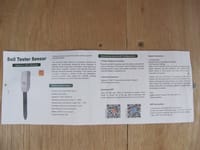
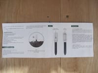
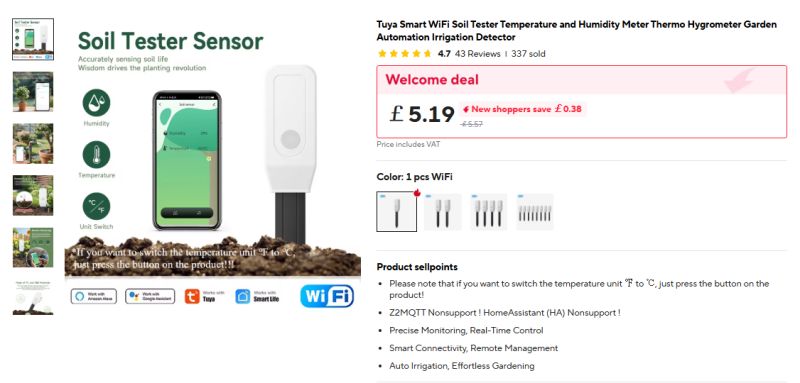
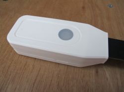
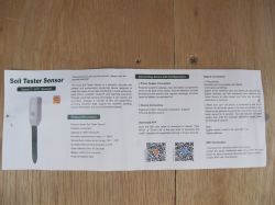
This is a 'Soil Tester Sensor' from Ali Express.
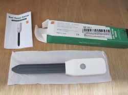
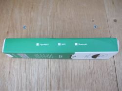
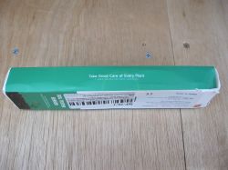
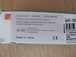
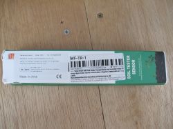
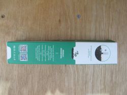
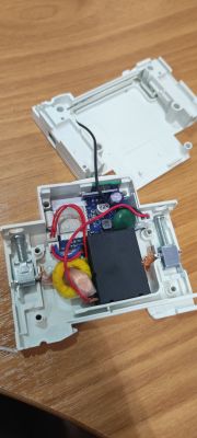
After popping off the battery cover, just 4 small cross-head screws allow for the removal of half the case
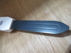
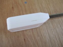
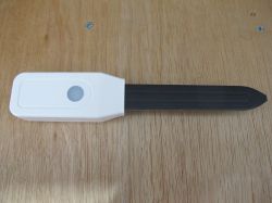
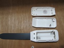
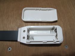
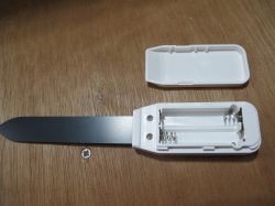
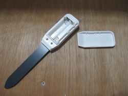
to reveal the main module - the T1-U-HL, a 16kb MindMotion MM32G0001 Arm Cortex-M0 TuyaMCU (also seen here) and an HGSEMI C5551 WSAH SOIC8 chip.
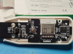
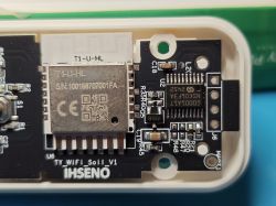
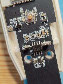
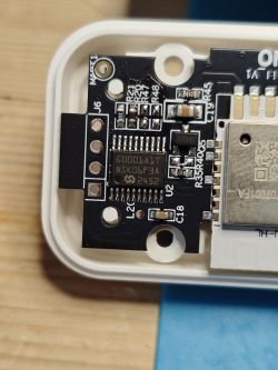
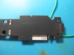
Unfortunately, the back of the PCB cannot be examined without de-soldering the battery terminals. There was little to be gained, however.
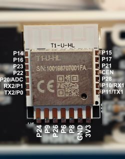
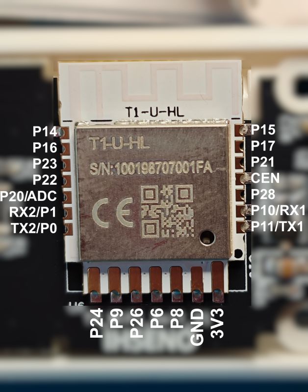
T1-U-HL details - https://developer.tuya.com/en/docs/iot/T1-U-HL-Module-Datasheet?id=Kdfp5j893qwxg
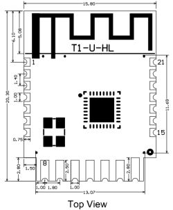
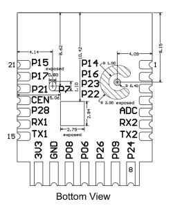
| Pin No. | Symbol | I/O type | Description | 1 | P14 | I/O | A normal GPIO pin, corresponding to Pin 19 on the IC. It can be reused as SPI_SCK. | 2 | P16 | I/O | A normal GPIO pin, corresponding to Pin 20 on the IC. It can be reused as SPI_MOSI. | 3 | P23 | I/O | A normal GPIO pin, corresponding to Pin 16 on the IC. | 4 | P22 | I/O | A normal GPIO pin, corresponding to Pin 15 on the IC. | 5 | ADC | I/O | An ADC pin, corresponding to P20 (Pin 13) on the IC. | 6 | RX2 | I/O | UART_RX2, corresponding to P1 (Pin 30) on the IC. | 7 | TX2 | I/O | UART_TX2 to print logs, corresponding to P0 (Pin 31) on the IC. | 8 | P24 | I/O | Support hardware PWM4, corresponding to Pin 17 on the IC. | 9 | P9 | I/O | Support hardware PWM3, corresponding to Pin 27 on the IC. | 10 | P26 | I/O | Support hardware PWM5, corresponding to Pin 23 on the IC. | 11 | P6 | I/O | Support hardware PWM0, corresponding to Pin 24 on the IC. | 12 | P8 | I/O | Support hardware PWM2, corresponding to Pin 26 on the IC. | 13 | GND | P | Ground pin. | 14 | 3V3 | P | 3.3V power pin. | 15 | TX1 | I/O | UART_TX1 to send user data, corresponding to P11 on the IC (corresponding to Pin 29 on the IC). | 16 | RX1 | I/O | UART_RX1 to receive user data, corresponding to P10 on the IC (corresponding to Pin 28 on the IC). | 17 | P28 | I/O | A normal GPIO pin, corresponding to Pin 12 on the IC. | 18 | CEN | I/O | The reset pin, active low, and pulled up internally. It is compatible with the designs of other modules. Corresponding to Pin 11 on the IC. | 19 | P21 | I/O | A normal GPIO pin, corresponding to Pin 14 on the IC. | 20 | P17 | I/O | A normal GPIO pin, corresponding to Pin 22 on the IC. It can be reused as SPI_MISO. | 21 | P15 | I/O | A normal GPIO pin, corresponding to Pin 21 on the IC. It can be reused as SPI_CS |
Feeding 3V through the batters terminals and from TX2 the boot log is captured at 115200 baud:
Code: Text
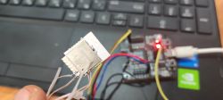
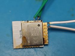
Unfortunately, the MindMotion MCU gets in the way of any flash read efforts on RX1/TX1, even with the MCU Nrst held low, so the module had to be hot air gun removed for flashing away from the MCU.
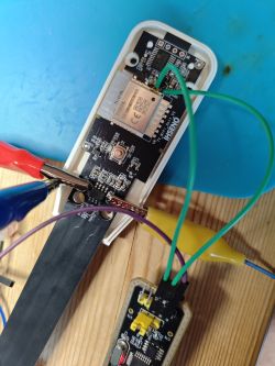
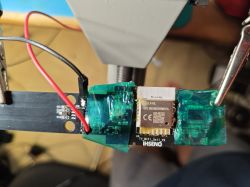
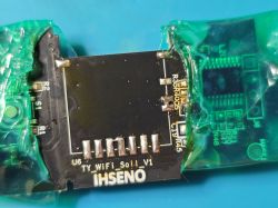
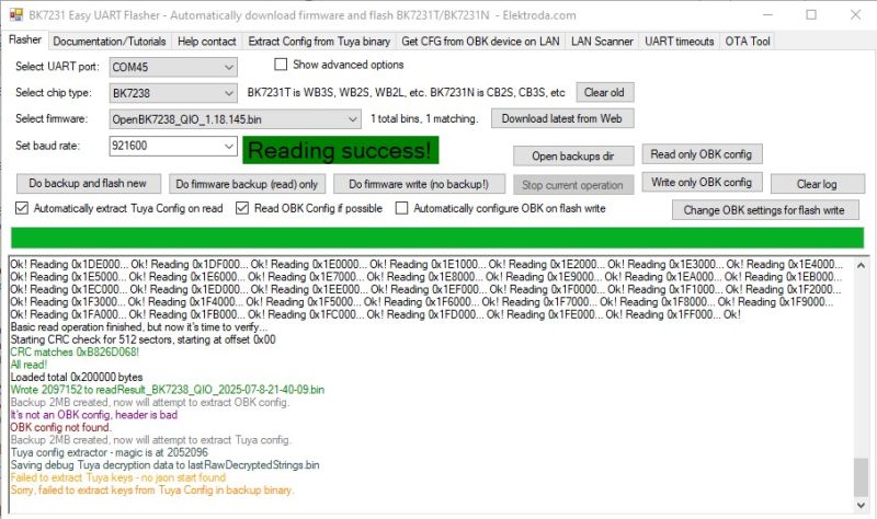
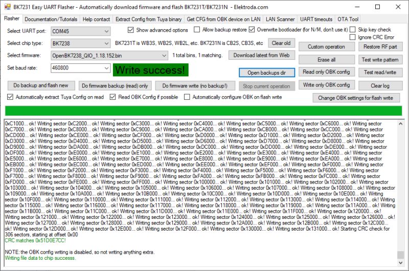
Easy Flasher reads whole flash successfully in BK7238 mode
Code: Text
As a precaution a backup is also taken with BKFIL
Code: Text
Code: Text
Regarding the TSSOP20 MM32 MCU (datasheet attached) we read this overview
Code: Text
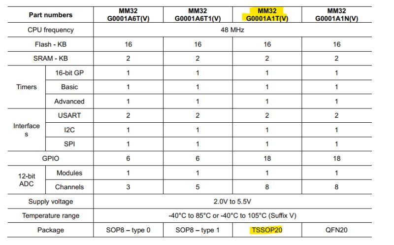
And to put how it connects to the 4 test pads and to the T1-U-HL in context:
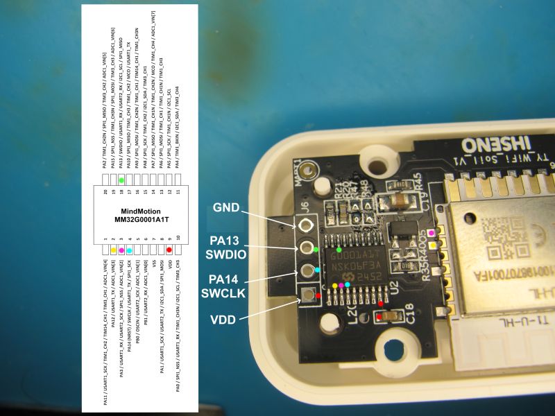
Maybe I should have another go at reading the flash with J-Link, I appear to have been unsuccessful with the other device.
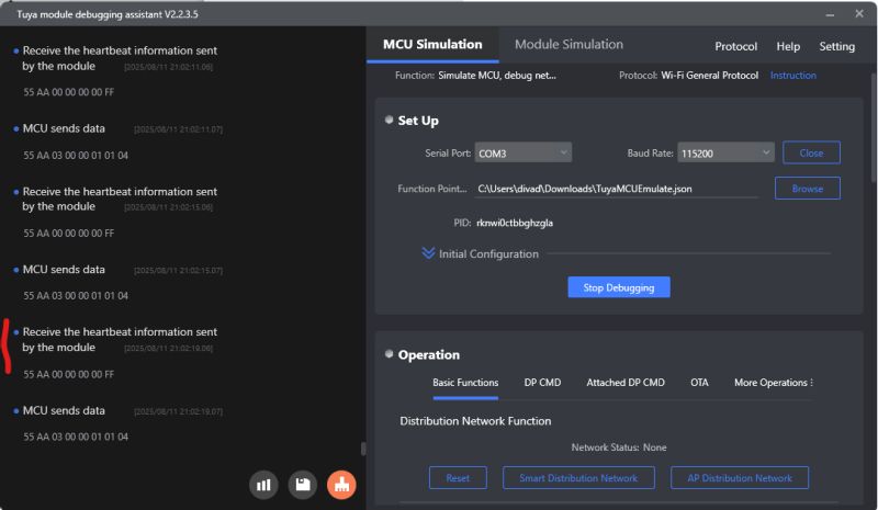
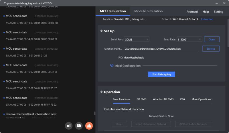
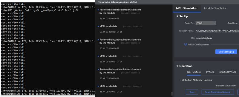
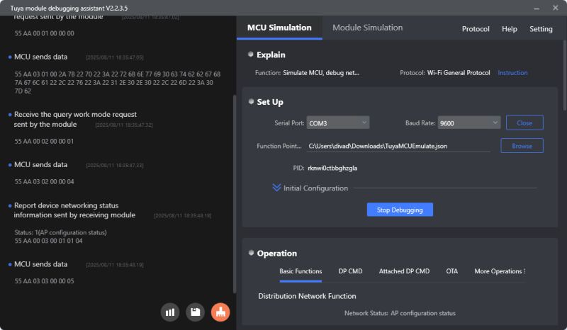
With the backup flashed to the NiceMCU and setup to talk to the Tuya Module Debugging Assistant with product ID rknwi0ctbbghzgla we can pair it with the Tuya app to check firmware versions, device appearance, options and readings
It seems it's just a glorified temperature and humidity sensor.
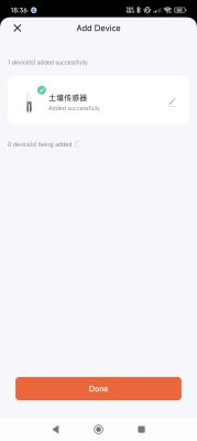
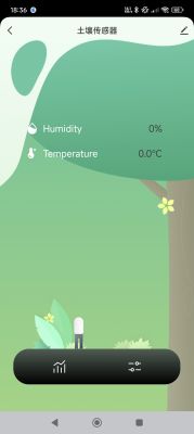
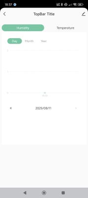
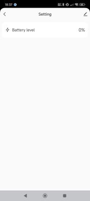
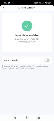
with the Tuya app linked to a dev account we can retrieve the dpIDs, needed for OpenBK7238 setup
Code: JSON
which when made pretty:
Code: JSON
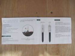
Interesting, separate dpIDs for Fahrenheit and a switcher dpID. I don't see a change function in the app. The manual offers no clues.
OpenBK7238 flashed over the top of factory firmware. I chose to overwrite the bootloader because keeping the factory BL meant OTA updates were not successful.
PCB and module cleaned up. Excess solder removed with solder braid.
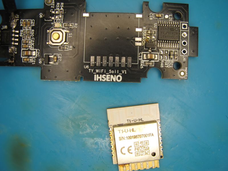
It appears the top two pads are only there to secure module to PCB - no traces on either side. It looks like P21 goes somewhere but I've yet to get any continuity to any component.
With the module soldered back in and OBK unconfigured, you get 20s from button-push wake-up until the MCU withdraws power from the T1 module. This gives just about enough time to navigate to the web app, create autoexec and set a starting script
With a basic starter:
Code: Text
I get no readings and no response to tuyaMcu_sendQueryState. Flag 26 ([UART] Use alternate UART for BL0942, CSE, TuyaMCU, etc) toggled doesn't change that.
This is where I will pause to investigate TuyaMCU comms to the NiceMCU with TMDA and to research the HGSEMI chip.
Cool? Ranking DIY


