logo elektroda
logo elektroda
X
logo elektroda

ESP32 - Suspension of the program when closing the solenoid valve in the CH and CUW system

globalinfo 2013 36
ADVERTISEMENT
Treść została przetłumaczona polish » english Zobacz oryginalną wersję tematu
  • #1 19426295
    globalinfo
    Level 13  
    Hello,
    I am controlling 3 circulating pumps and one solenoid valve in a CH and CUW system using ESP32.
    I have a problem because when closing the solenoid valve the program crashes you.
    When switching the pumps on and off and opening the solenoid valve it has never crashed.
    The ESP is powered via USB from a power supply hooked up to a small UPS.
    The pumps and electro-valve are powered by ~230V - wires of about 2.5m each.
    I also added a 2200uF capacitor at the ESP power supply but this did not help.
  • ADVERTISEMENT
  • #3 19426327
    globalinfo
    Level 13  
    Kuniarz wrote:
    Physically switch with relays ? Opto-isolation ?
    .
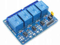
    Yes- 5V relays with opto-isolation - same are for pumps.
  • #4 19426333
    Kuniarz
    Moderator of Designing
    You can power up the ESP from a powerbank for example on a trial basis and then you will know if the problem is interference on the power supply.
    It's also a good idea to use gasifier circuits on the relay contacts - google will help.
    Helpful post? Buy me a coffee.
  • #5 19426340
    globalinfo
    Level 13  
    Kuniarz wrote:
    You can power up the ESP from a powerbank for example on a trial basis and then you will know if the problem is interference on the power supply.
    It's also a good idea to use a circuit put out on the relay contacts - google will help.
    .
    The valve is barely 6W.
    UPS is not enough?
    It should protect against interference.
  • ADVERTISEMENT
  • #7 19426450
    khoam
    Level 42  
    globalinfo wrote:
    UPS not enough? It should protect against interference.
    .
    But not those induced in the wires and paths due to vibration of the relay contacts. The suggestion of using an extinguisher circuit is therefore most appropriate.

    globalinfo wrote:
    I still added a 2200uF capacitor at the ESP supply but it didn't help.

    This ac couldn't help much, but I would probably add a 100µH choke on the power supply to the ESP or between the ESP and power supply grounds.
  • #8 19426712
    globalinfo
    Level 13  
    khoam wrote:
    The suggestion to use an extinguisher system is therefore most appropriate.
    .
    The only thing is whether such a quencher won't jam my solenoid valve has 6W.
    I have 0.470uF capacitors.
    I have given a 100 ohm resistor and the valve works without giving a control signal.
  • Helpful post
    #9 19426866
    khoam
    Level 42  
    The capacitance value of the capacitor is, in my opinion, far too high and with this resistor value it should be in the range of 10-22 nF. You have a nomogram for calculating these values attached.
    How specifically did you connect the RC bipolar?
  • #10 19427134
    krzbor
    Level 27  
    I once built a circuit based on ESP8266 and SIM800 (GSM module). The antenna of the SIM800 module was just a few centimetres away from the ESP. I expected interference. Problems did indeed arise - the chip would unexpectedly reboot 1-2 times a day. It was not critical, so I left it. Later I changed the programme a bit and the reboots were almost all the time. Something didn't feel right here - it couldn't be the SIM800's fault. I changed the program and eliminated returning a String object through a function to passing them through a variable. The problems went away and the circuit stopped rebooting. I'm writing about this because sometimes we don't notice the error in our own code, and look somewhere else. It seems to me that the ESP is more likely to reboot rather than fail if there are 'electrical' problems. So it's worth doing a simple test - disconnect the solenoid circuit completely (the optoisolator diode), and put an LED in its place (with a resistor). If everything works, then the programme is probably correct. The second step is to leave the optoisolator and relay in place, and disconnect the solenoid valve. This will eliminate the influence of the solenoid valve itself.
  • #11 19427387
    globalinfo
    Level 13  
    khoam wrote:
    The capacitance value of the capacitor is in my opinion far too high and with this resistor value it should be in the range of 10-22 nF. You have a nomogram for calculating these values attached.
    How specifically did you connect the RC bipole?
    .
    It does indeed come out too big.
    I will use 22nF - waiting for shipment .

    Added after 3 [minutes]:

    krzbor wrote:
    It is therefore worth doing a simple test - disconnect the solenoid circuit completely (optoisolator diode), and put an LED (with resistor) in its place. If everything works, then the programme is probably correct. The second step is to leave the optoisolator and relay in place, and disconnect the solenoid valve. This will eliminate the effect of the solenoid valve itself.
    .
    I tested with the relays alone without the pumps and solenoid valve connected - it did not hang up.
    In addition to this, 2 more relays are switching the fans on and off at 5V - it does not hang up either.
    Only when the solenoid valve closes.
  • ADVERTISEMENT
  • #12 19427419
    krzbor
    Level 27  
    globalinfo wrote:
    Tests I carried out with relays alone without pumps and solenoid valve connected - it did not hang up.
    In addition to this, 2 more relays are used to switch the fans on and off at 5V - it does not hang up either.
    Only when the solenoid valve closes.
    .
    I see two possibilities - either something is "sowing" on the mains, or the solenoid valve is generating some large electromagnetic interference.
    To eliminate the first possibility connect (for a test) the solenoid valve to a different phase, or as colleagues advised power your system from the battery.
    To eliminate the second possibility, move both systems as far apart as possible - first the solenoid valve from the ESP + relay, and if that doesn't help, leave the relay at the solenoid valve and move the ESP away.
    If this does not work either, power the relay circuit from an independent power supply, so that ESP is only connected to the optocoupler diode (without equalizing the ground potentials of both circuits, i.e. with full galvanic isolation on the optocoupler).
  • #13 19427982
    globalinfo
    Level 13  
    I fitted two circuits with suppressors (100 ohm resistor + 22nF capacitor) to the switching contacts for the solenoid valve.
    At this point the circuit is working stably.
    I will leave it for two days for testing.
  • #14 19428027
    khoam
    Level 42  
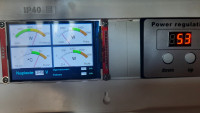
    Nice those 'analogue' displays look nice. Any library? ;)
  • #15 19428099
    globalinfo
    Level 13  
    khoam wrote:
    Cute those "analogue" displays look. Any library? ;)
    .
    TFT_eSPI tailored to my needs - Link
  • #16 19429478
    globalinfo
    Level 13  
    Well unfortunately the test failed, the suspension happened.
    I'll try adding a filter to the solenoid valve - it's about 2m from it to the relay.
    I'm going to put a 0.470uF and a 1k/1W resistor - hopefully it will help.
  • #17 19429493
    khoam
    Level 42  
    After what time did this happen and was it definitely when the valve was switched on?
  • #18 19429512
    globalinfo
    Level 13  
    khoam wrote:
    After what time did this happen and was it definitely at the time the valve was engaged?
    .
    At the time of starting to close the valve - it failed today at 12:17 and a second time at 13:20.
    When opening the valve and switching the pumps on and off there were no suspensions.
  • #19 19429659
    khoam
    Level 42  
    globalinfo wrote:
    100 ohm resistor + 22nF capacitor
    .
    What is the power rating of this 100 ohm resistor?

    globalinfo wrote:
    I'll give 0.470uF and a 1k/1W resistor - hope it helps.

    In my opinion these values are not correctly selected ie not in accordance with the nomogram I posted earlier.
  • #20 19429664
    TvWidget
    Level 38  
    Everything indicates that the device you have created is both a source of interference and is itself sensitive to interference. To some extent you have solved one problem but the other still remains.
  • #21 19429673
    khoam
    Level 42  
    globalinfo wrote:
    In the moment it starts closing the valve
    .
    Did it hang up before closing the valve? It would be a good idea to have the serial port monitor permanently connected, sending and logging significant program actions, at least until the problem is resolved.
  • ADVERTISEMENT
  • #22 19429694
    globalinfo
    Level 13  
    khoam wrote:
    globalinfo wrote:
    In the moment it starts closing the valve
    .
    Did it hang up before closing the valve? It would be a good idea to have the serial port monitor permanently connected, sending and logging significant program actions, at least until the problem is resolved.


    It hung up at the moment when the relay applied voltage to the valve.
  • #23 19429826
    khoam
    Level 42  
    krzbor wrote:
    I think the ESP will reboot rather than fail in the event of 'electrical' trouble.
    .
    I'm beginning to agree with the opinion of colleague @krzbor that the problem may have multiple causes. I continue to believe that the extinguisher system is needed, but in a normal situation in the ESP the WDT should work (it is on by default) and the system should just reset. Are you sure the problem is with the ESP itself? Or perhaps the display controller circuit?
  • #24 19429919
    Slawek K.
    Level 35  
    Or the programme itself.

    Greetings
  • #25 19430118
    globalinfo
    Level 13  
    khoam wrote:
    Are you sure the problem is with the ESP itself? Or maybe the display controller chip?
    .
    I'm sure about the program and controller - I tested it without connecting the solenoid valve and pumps - it never crashed or reset.
    Of course there was a bit of fiddling when connecting the display, but that got it right.
    Below is a link to a video of the circuit during the test .
    Link .
    Link2 - display driver tests
  • #26 19430168
    khoam
    Level 42  
    globalinfo wrote:
    I am confident in the program and controller - I tested it without the solenoid valve and pumps connected - it never crashed or reset.
    .
    I understand that, but my question was about when the system is running on target. What specifically does this "suspension" manifest itself as?
  • #27 19430618
    globalinfo
    Level 13  
    khoam wrote:
    globalinfo wrote:
    I am confident in the program and controller - I tested it without the solenoid valve and pumps connected - it never crashed or reset.
    .
    I understand that, but my question was about when the system is running on target. What specifically does this "suspension" manifest itself as?
    .
    Specifically this - the display goes black, the relays to the fans stop working (don't switch on), the power consumption controller does not receive control signals, no data is sent to the server - this state persists until the ESP is switched off and on.
  • #28 19430661
    Kuniarz
    Moderator of Designing
    Maybe make a simple program which, for example, switches the valve on and off every few seconds and so on in an infinite loop. You will then be sure that the problem is with the valve control.
    Additionally - you wrote earlier that you have 5V relays, admittedly with opto-isolation, but something seems to me that this isolation doesn't do anything, as you probably have the coil feed from the same source as the rest.
    Helpful post? Buy me a coffee.
  • #29 19430674
    globalinfo
    Level 13  
    Kuniarz wrote:
    Additionally - you wrote earlier that you have 5V relays, admittedly with opto-isolation, but something seems to me that this isolation does not give anything, because you probably have the coil supply from the same source as the rest.
    Yes - I checked the operation - everything connected except the solenoid - works without problems.
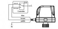
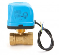
    I should add that the solenoid valve is not on a solenoid but has an actuator on a ~230V motor.
    Can you suggest to which pins to connect the 100nF capacitor at ESP32 as I have power via microUSB.
  • #30 19430994
    khoam
    Level 42  
    globalinfo wrote:
    Can you suggest to which pins to connect the 100nF capacitor at the ESP32 as I have a power supply via microUSB.
    .
    Power supply pin 3V3 (2): capacitors 100nF (ceramic) and 1000uF (as close as possible)
    EN pin (3): 100nF capacitor (ceramic, as close as possible)

    ESP32 - Suspension of the program when closing the solenoid valve in the CH and CUW system

Topic summary

The discussion revolves around an issue with an ESP32-based system controlling three circulating pumps and a solenoid valve in a central heating (CH) and cooling water (CUW) setup. The program crashes specifically when the solenoid valve closes, while operations involving the pumps and opening the valve do not cause failures. Suggestions include using opto-isolated relays, testing with a power bank to rule out power supply interference, and implementing snubber circuits to mitigate electromagnetic interference from the solenoid valve. The user has tested various configurations, including adding capacitors and resistors to the circuit, and has observed intermittent stability. Ultimately, the user reports that the system has not crashed for an extended period after implementing suggested changes, although issues with data uploads to the server persist.
Summary generated by the language model.
ADVERTISEMENT