logo elektroda
logo elektroda
X
logo elektroda

Wemos D1 mini - control of a Majfriend double relay via GND

unky 837 5
ADVERTISEMENT
Treść została przetłumaczona polish » english Zobacz oryginalną wersję tematu
  • #1 20643765
    unky
    Level 18  
    I purchased a double relay from Majfriend. I wanted to control it from the Wemos. Unfortunately it turned out that the relay is controlled by GND and not by a high state. Is it possible to program the outputs in Wemos so that GND appears on them? Previously I had relays controlled by a low/high state and I controlled them without any problems from D1 and D2 outputs in Wemos.
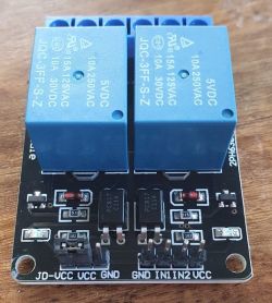
    Wemos D1 mini - control of a Majfriend double relay via GND .
  • ADVERTISEMENT
  • #2 20643786
    viayner
    Level 43  
    Hi,
    from what I have read, the Wemos D1 is based on ESP8266 chips, which are programmable microcontrollers. There are no problems sending a low or high state to a given port - it's just a matter of setting it up in code.
    If you don't want to change anything, then add an inverter on each relay control output (NPN transistor with resistor).
    Greetings
  • ADVERTISEMENT
  • #3 20643792
    unky
    Level 18  
    The low/high state is probably not a GND output after all? In order for the relay to operate on the IN1 pin I need to provide GND. I manually tested this without Wemos which wouldn't drive the input on the relay for me. If nothing is connected to pin IN1 then the relay is open. When GND is applied to IN1, the relay closes. My question is how to connect GND from Wemos to D1 output and is it even possible?
  • ADVERTISEMENT
  • #4 20643827
    viayner
    Level 43  
    Hello,
    Maybe read the basics of digital technology. In simple terms, the H high state is almost the supply voltage Ucc, and the L low state is almost GND. "Almost" because there are switching elements in the structure that have non-zero resistance and minimal voltage drop.
    In your case, passing the L state is equivalent to GND.
    From what I can see, you have a transistor there, so if you don't want to modify the code, move resistor R1/R4 on IN to ground, and then the LED cathode of the transistor will become the high state control.
    http://wiki.sunfounder.cc/index.php?title=2_Channel_5V_Relay_Module
    Greetings
  • ADVERTISEMENT
  • #5 20644976
    unky
    Level 18  
    I can modify the code in ESPHome, but what should I change? I have so:

    switch:
    - platform: gpio
    name: "Open Garden Gate"
    pin: D1
    id: opengate_d1
    restore_mode: ALWAYS_OFF
  • #6 20645135
    inot
    Level 37  
    You would first need to familiarise yourself with the basics of ESPHome.
    Output state realisation:
    Code: Arduino
    Log in, to see the code


    Also the following example may be helpful:
    Link

    Explanation of the issue with feeding GND to the output:
    Quote:
    Setting inverted to true means that turning the switch on will output 0v on the gpio. Turning the switch off will output 3.3v.
    Setting inverted to true means that turning the switch off will output 3.3v.
ADVERTISEMENT