Hi, I would like to ask for help with the connection of the fox shutter module.
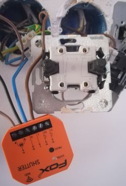
So far it looks like this. In the module:
1 on the left is the wire from the shutter that raises it up.
The 2 on the left is the wire from the shutter that lowers it.
3 on the left is the N from the power supply. (all the N from the blinds clipped together with the N from the power supply, I added an extra wire to the cube and connected it to the module).
The 4 on the left is the L from the power supply.
Is this ok?
The question is how to connect the wall switch now?
If I connect the up/down control to the switch and then to the control unit in S1 and S2 (5th and 6th input from the left), what then? In the wall switch there is then one place left with the description L.
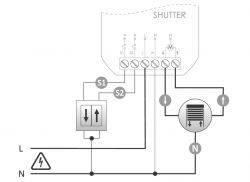
I have uploaded a diagram and a real photo below.
.
.
Added after 5 [hours] 21 [minutes]:
---- Update ----
So far I've done the configuration via the app and it works remotely, but I still don't have the connector connected.
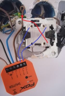
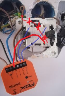
Generally there is voltage on S1 and on S2 (5th and 6th from the left) all the time. Is a diagram like the one below OK? Is this how it should be connected?
1 left - from motor, direction down
2 left - from motor, direction up
3 left - extra cable from the cube (all N from the blinds connected in the cube together with N from the power supply, I added an extra wire to the cube and connected it to the module)
4 left - L from power supply
5 from left (S2) - additional wire going in the down direction in the connector
6 left (S1) - additional wire going in up direction in the connector
There should be an L from the power supply (branched wire in the wago) connected to the connector in the L field?
In this configuration there is still voltage on the switch in each of the 3 inputs. Surely it is only when the button is pressed that a particular circuit closes and the shutter goes up/down? Previously, the voltage on the switch was still on the L input, and only appeared on the directional input when the wall button was pressed. This probably blocked both directions from being accidentally pressed? Although the switch itself has a mechanical interlock, it is not possible to press both directions at the same time.
I would appreciate an explanation. Thanks!
.


