logo elektroda
logo elektroda
X
logo elektroda

Connecting Shelly 2.5 to Bister RCS4E Central Roller Shutter Switches

radekkowalik1986 1143 10
ADVERTISEMENT
Treść została przetłumaczona polish » english Zobacz oryginalną wersję tematu
  • #1 20000499
    radekkowalik1986
    Level 2  
    Welcome,

    I would like an answer to the question about the possibility of connecting Shelly 2.5 to the central switch of the roller shutters. My roller shutter installation is based on Bister model RCS4E controllers. In each box at the roller shutter under the switch sits such a controller. In addition, I have a group switch for 4 roller shutters in the living room and a group switch for all the roller shutters. As time has gone on, I have started to think about automation at least on a central level, but I have my doubts as to whether this can be done. Attached is a photo showing what one of the group switches looks like. There are 3 wires coming out of the box and each is live as if L1, L2, L3. When L1 and L2 are connected, the roller shutters close, and when L1 and L3 are connected, the roller shutters stop and open when pressed again. Is it possible to connect the Shelly 2.5 controller to this? I would add that there is a neutral wire in the box upstairs if it would be needed to close the circuit. Is it possible to arrange this in this box or do I need to combine in the switchboard and I do not want to do this myself.
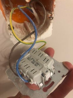
    Connecting Shelly 2.5 to Bister RCS4E Central Roller Shutter Switches .
  • ADVERTISEMENT
  • #2 20001064
    kokapetyl
    Level 43  
    Colleague.
    The first thing that strikes one's eye is an installation done defectively (I don't know who did it).
    The protective conductor must not be used for any other purpose than protection.
    The photo shows that it was used incorrectly (as a phase wire).
    From my side, it is a piece of advice, ask the contractor to do the installation correctly (the wire should be a minimum of four conductors (not as it is)
  • ADVERTISEMENT
  • #3 20004412
    sk1977

    IT specialist
    If you tighten the N then it is possible to Shelly 2.5 connect.
    Only one is L - the other two are control - there is no L1, L2, L3.
    There are 2 ways to connect - either a connector in parallel to Shelly 2.5 or a connector to Shelly 2.5 and only Shelly 2.5 controls.
    The colours of the wires - as the Col. above writes - are not suitable, in which case they can be properly marked on both ends with shrink sleeves, for example. Lack of such markings is unfortunately a very common problem.

    EDIT: When tightening N, make sure it is "through the same RCD" as L.
    Helpful post? Buy me a coffee.
  • ADVERTISEMENT
  • #4 20004811
    kokapetyl
    Level 43  
    sk1977 wrote:
    as Col. writes above they are not suitable, in which case they can be marked properly with t-shirts at both ends
    .
    and you think the matter will be resolved?
  • #5 20004879
    sk1977

    IT specialist
    This is a commonly used solution. Unfortunately so is connecting a roller shutter switch in this way - which is not correct.
    As far as I remember (and I may be wrong - in which case please correct me with the applicable Standards), it is permissible to change the function of a cable provided that it is permanently marked at both ends.
    Helpful post? Buy me a coffee.
  • ADVERTISEMENT
  • #6 20004975
    kokapetyl
    Level 43  
    sk1977 wrote:
    (and I could be wrong - in which case please correct me with the applicable Standards) a change in the function of the conductor is permissible provided it is permanently marked at both ends.

    What about the provision that each section of the new installation must have a protective conductor?
  • #7 20005005
    sk1977

    IT specialist
    kokapetyl wrote:
    And what about the provision that each section of new installation must have a protective conductor?
    - where is such a provision? In the regulation § 183. 1.? Does it also apply to the control installation or only to the electrical installation - "in distribution and consumer circuits"? Here it is true that there is an L, but this is not a supply installation (no N).... According to the instructions, there should be red (L) and brown and black (control) wires.
    Helpful post? Buy me a coffee.
  • #8 20005036
    kokapetyl
    Level 43  
    sk1977 wrote:
    There is admittedly an L, but this is not a supply installation (no N)...
    .
    As you yourself pointed out, it is also the "N" that is used, not exactly as it should be (I don't know exactly how it is in the regulations, but in my opinion it is also wrong), maybe I am wrong? However, assuming a correctly laid installation, there would be no problems :cry: .
  • #9 20005100
    sk1977

    IT specialist
    kokapetyl wrote:
    As you yourself have noticed, it is also the "N" that is used, not exactly as it should be
    - this is not what I noticed. On the contrary. I pointed out the absence of N (it's not needed for anything here), i.e. it's not a supply circuit - neither a receive nor a distribution circuit. From a function point of view - it is a purely control circuit. So it is difficult here to apply regulations or standards as for a consumer circuit.
    I agree that wires with reserved colours should not be used. It is also unclear whether the installer knew how this circuit would be used, maybe the concept changed and this change resulted in such a situation.
    Helpful post? Buy me a coffee.
  • #10 20008340
    radekkowalik1986
    Level 2  
    sk1977 wrote:
    Only one is L - the other two are control - there is no L1, L2, L3
    .
    When all the wires are unplugged from the connector and I check them with a tester then each wire separately is live.

Topic summary

The discussion revolves around the feasibility of connecting a Shelly 2.5 controller to Bister RCS4E central roller shutter switches. The user describes their roller shutter setup, which includes individual controllers for each shutter and group switches for centralized control. Responses highlight concerns about the existing wiring, noting that the installation appears to be incorrect, particularly regarding the use of protective conductors. Suggestions include ensuring a neutral wire is available and properly connecting the Shelly 2.5 either in parallel or as the sole controller. The importance of correctly marking wire colors and adhering to electrical standards is emphasized, with some debate on the regulatory implications of the current wiring setup.
Summary generated by the language model.
ADVERTISEMENT