Elektroda.com
Elektroda.com
X

Analyzer - meter of 230VAC network parameters - single phase.

futek2 8538 114
This content has been translated flag-pl » flag-en View the original version here.
  • #61
    Natanoj
    Level 11  
    Can I ask for a lead on the measuring probes-grippers from the project? Everything I can find at an acceptable price does not encourage me to plug into a live circuit.
  • #62
    Dariusz Goliński
    Level 22  
    And good.
    I switched to another computer and Flasher doesn't work there either.
    I downloaded the flash download tool 3.9.3 from the net, selected the ESP32 board, selected the meter's bin and entered the address 0x00000. Well, it's supposed to load, it says it's SUCCESS. I disconnect and reconnect the power and I don't see WIFI or flashing blue light.
    I verified with the ESP RF Test EN program whether this board has sufficient capacity and it turns out that it is OK.
    I connected the terminal to the port and the board reports itself during startup. Pressing the BOOT button does nothing. Holding down the BOOT button and the EN button for a moment (i.e. reset) puts the board in the file receiving mode. (At least that's how the terminal shows it)
    Do you have any other idea what else I can do?
  • #63
    jarekgol
    Level 31  
    futek2 wrote:
    These two transformers in brown brine
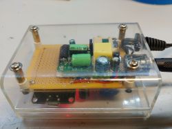
    smart was missing :)
    I think I uploaded this ESP flasher to my 8266, some wifi appeared, I can connect, but when I enter the gate address from my phone, I have an error. How is this supposed to work in theory? And only under Win? Because I prefer Linux (but I have some xp, 7, 8, 10 at home).
    When I get the right proc, I'll look for what it can be uploaded, but it hasn't arrived yet.
  • #64
    futek2
    Level 19  
    Hello.
    I am replying to the last 3 posts in turn.
    As for the sensors for measuring the current, they are available at a price of about PLN 27, they have become a bit more expensive. Because I checked and there is a lot in a different measurement range on a well-known auction site.
    And as for the uploaded software, if the tile starts, which can be seen on the terminal, it tries to connect to the router for the first dozen or so seconds, and if I pass this time and it does not connect to the router, it goes into AP mode, which can be seen in the preview from the terminal, only warmly please wait and AP will appear and will be seen on WIFI. The address 192.168.10.1 is the gateway address.
    And as for the last post, ESP8266 is a completely different processor from ESP32 and even if you manage to upload the soft, it will not work. Must be ESP32. Perhaps the name of the board is confusing, but ESP8266 and ESP32 are quite different versions of boards on which other types of processors with different architecture are soldered. ESP32 is much better than ESP8266 and has more computing power.
    That's for clarification.
    Regards and wish you success.

    Futek2
  • #66
    futek2
    Level 19  
    Hello.
    And after uploading, the program starts on ESP32?
    All options work but no measurement results.
    Please show off how it works with screenshots.
    Futek2
  • #67
    Dariusz Goliński
    Level 22  
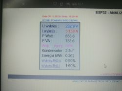
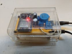
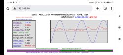
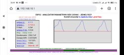
    This is what my analyzer looks like.
    Analyzer - meter of 230VAC network parameters - single phase. Analyzer - meter of 230VAC network parameters - single phase. Analyzer - meter of 230VAC network parameters - single phase.
    I noticed that every few minutes he likes to break the connection and reconnect.
    I already have a plan for the measurements but could you add a meter for the energy used?
    I want to use it in a place where there is no internet and the cell phone does not work there, so sending data to the server will fail.
  • #68
    futek2
    Level 19  
    Hello
    My first question, did you have problems calibrating the voltage and current range?
    And as for the energy, it is counted from the beginning of switching on, it is in the window on the left, the second position from the bottom.
    As for the loss of connection, maybe the signal from the router is weak.
    I think that there was no problem with the configuration either the first time you started it as an AP.
    Congratulations that you got everything assembled and started without any problems. It came out very nicely put together.
    Regards and enjoy using the meter
    Futek2
  • #69
    Dariusz Goliński
    Level 22  
    There was no problem with the calibration.
    The results are slightly floating in relation to the meter and I do not know what is the reason for this, but it worked.
    I am not connecting through the router. Direct connection computer --> ESP.
    So this kWh indicator resets at the start and counts ascending?
  • #70
    futek2
    Level 19  
    The kWh energy is accrued incrementally and starts after each ESP reset.
    ESP can be reset via the website
    /esp
    And I did it so that you can reset when the meter is in a hard-to-reach place but within WIFI range.
    This slight float may be due to the smoothing of the readings to get rid of the noise.
    But I chose the averaging by many tests
    trials.
    I think you already have the first conclusions after the measurements of your network and sinusoid distortions and harmonic content.
    Futek2
  • #71
    khoam
    Level 42  
    Dariusz Goliński wrote:
    There was no problem with the calibration.

    What exactly did this calibration consist of and what standard meter was used?

    futek2 wrote:
    The kWh energy is accrued incrementally and starts after each ESP reset.

    So even after an accidental ESP reset, the history of measurements is lost, even in a truncated range?
    futek2 wrote:
    Once again, I inform you that calibration is only necessary with potentiometers because I chose the middle of the ADC range

    What specific ADC input voltage range has been selected?
  • #72
    futek2
    Level 19  
    Hello
    Regarding the reported problem
    on intermittent loss of WIFI connection. Then I will try to divide the tasks into two processor cores. For one to handle WIFI and the other to read measurements and calculate them.
    Perhaps this will eliminate the problem of periodic loss of connection after WIFI. And as for the selected measurement range, the description is justified in one of the initial posts and it also follows from the diagram - reference voltage.
    Best regards and I wish you satisfaction with the user of the analyzer

    Futek2
  • #73
    khoam
    Level 42  
    futek2 wrote:
    Regarding the reported problem
    on intermittent loss of WIFI connection. Then I will try to divide the tasks into two processor cores. For one to handle WIFI and the other to read measurements and calculate them.

    I'm afraid that's not the way. Arduino Core for ESP32 is based on FreeRTOS and the key to "success" is proper prioritization and timing of individual tasks, regardless of which core they are performed on. In addition, the first post shows that ESP with an external antenna was not used, which only worsens the situation in terms of WiFi availability.

    futek2 wrote:
    And as for the selected measurement range, the description is justified in one of the initial posts and it also follows from the diagram - reference voltage.

    In my opinion, not really, but if the Author does not want to answer quite simple questions, then he does not have to.
    However, the diagram shows that the ADC inputs are not protected against noise as recommended by the manufacturer: link . It is also unknown whether multisampling was used to mitigate the effects of noise.

    What about:
    khoam wrote:
    So even after an accidental ESP reset, the history of measurements is lost, even in a truncated range?
  • #74
    Dariusz Goliński
    Level 22  
    I used SANWa 5000 for calibration.
    If it's not a problem, I'll ask for this reset button.
    I was supposed to bring a reset to the housing today, but if it was software, it would be a better solution.
  • #75
    futek2
    Level 19  
    Yes, a quick rest is possible, just like / config, we also write / esp
    And there's a reset.
    As for the noise, the tests showed that adding a filter to the inputs significantly distorts the measurement of the sine wave shape and THD parameters, and that's why I did it in software after the measurement.

    It will be added in the next version
    Futek2.
  • #76
    jarekgol
    Level 31  
    @futek2 How much current does it take from 5V?
  • #77
    futek2
    Level 19  
    Hello.
    The first is ESP32 depending on what it does, but when it has active WIFI and there is a connection, it is about 0.5A and so within about 0.25A.
    I tested on a lithium cell, removing it from the laptop package, ESP32 worked for 3 hours,

    Perhaps the new link would have even better working time results.

    Attached are the newest version of the meter software with minor corrections and added RESET according to the col. Darius Golinski
    This is available in the lower left pane next to the signal level.
    I would like to remind you that we can update without removing the ESP32 from the meter, it is possible via WIFI xxx.xxx.xxx.xxx/new
    XXX is the IP address in case of not connecting to the router when it works as an AP 192.168.10.1/new

    A convenient option has also been added that when we connect to the meter via WIFI in AP mode, we can enter esp32.pl and we will also connect with the meter
    It works in AP mode when the meter is not connected to your home router.

    And people who have phones OS APPLE it is enough to enter in the browser
    esp32.local but the meter must be connected to the router.

    Futek2
  • #78
    jarekgol
    Level 31  
    Hmm, the proc came, I'm trying to upload and I have a problem. I'm trying to upload it to linux.

    Code: bash
    Log in, to see the code


    And now I have an error:
    Code: bash
    Log in, to see the code


    update:
    I added ESP32 to Platformio, wrote a led blink under Arduino and uploaded it - it went, it flashed.
    Then I uploaded the bin file to different addresses and it turns out that the correct address is 0x10000

    @futek2 you should probably provide 2 more files - bootloader and some partition table so that it can be uploaded from scratch.
    Analyzer - meter of 230VAC network parameters - single phase.
    For now, a bare DEVKIT board without peripherals.
  • #80
    jarekgol
    Level 31  
    futek2 wrote:
    Hello.
    Something is different because ARDUINO IDE uploads from 0x0000
    It's a description
    http://100-x-arduino.blogspot.com/2018/10/flash-esp32-jak.html

    if you look at this screen with a frame + description under it, then under 0x1000 there is a bootloader (or a loader of the next row, because something must give these errors after rs232 that it cannot read the address 1000 that I saw ;) , under 0x8000 the partition table, whatever it is, I don't know, and under 0x10000 the user program, and this address 0x10000 in this screenshot you can see, 164kB was written under it.

    I suspect that once you have this board saved by Arduino, then it goes easier. What are you loading it with the first time?
  • #81
    futek2
    Level 19  
    I upload differently when I try to do it with ARDUINO IDE and if it has bin, it's a different program. I've never had problems with any board I have. But I found descriptions of people having problems.
    I can't explain this problem, maybe a coincidence.
    Futek2
  • #82
    jarekgol
    Level 31  
    In my opinion, the case is that to run your project (without the source and your own Arduino copy) you need 3 files and information where to upload them, and you give one and without the address. I avoid the Arduino IDE, but it doesn't seem to have the option to upload "other" binaries https://arduino.stackexchange.com/questions/4...ash-pre-compiled-bin-files-into-nodemcu-using -ardunio-ide . I'm writing this because more people might run into this problem. You get such a tile with Allegro and what's next? There are no instructions on how to upload it in the first post or anywhere else. I understand that you keep the sources to yourself, and thank you for sharing your work, but in that case, the upload instructions would be useful.
    So if someone has a problem with uploading, I recommend first uploading the blink from Arduino, and then writing the friend's binary under 0x10000.
  • #83
    Dariusz Goliński
    Level 22  
    I'll say it.
    I also had a problem with uploading this file from the attached esp flasher. By the way, if someone can't handle the attached flasher, I don't know how they will manage to build this device. There is really no philosophy.
    The author states that it should be uploaded to the address 0x0000 and this is the correct address and file.
    Nothing else is needed.
    I failed to upload the flash file that the author attached.
    Then I used this flash from the esp manufacturer's website and it didn't work either. I put it to the address 0x1000 and it was also a linden. It even started throwing errors across the terminal.
    Only the program I attached in the post worked. I uploaded to address 0x0 and it worked from the first time.
    Maybe it's a problem with the libraries in the system but it worked out in the end.
  • #84
    futek2
    Level 19  
    Hello, interested in the meter - analyzer.

    After many tests with various boards that I rented, I managed to solve the problem with uploading the firmware.
    Because there were problems that I had not encountered before, and they resulted from the comments of colleagues.

    Uploading the software is now trivially easy, and this description came to the rescue:

    https://github.com/Jason2866/ESP_Flasher/releases

    Both versions of the program are attached.

    I tested the program on the ESP8266 and ESP32 board - it works on both versions without a problem.
    The author of the project deserves recognition and words of praise.

    Please do not treat that the compiled soft on ESP32, uploaded to ESP8266 will work and vice versa.

    Attached are photos of how the software upload process works and does not require additional files.

    It is important for ESP32 to press the BOOT button on the right side of the MINI USB connector and hold it for a while, this must be done several times for the whole process to end successfully.

    And what's important, it clears the memory before uploading, which you need to remember.
    I do not recommend it for updating the software because the data saved during configuration will be deleted.
    Updating the software is recommended by the website, because it does not delete the configuration data.
    Of course the program works with boards that have USB!!

    The program also has a terminal window and you can see what is happening after uploading the software and starting it.
    I think that my oversight has already been solved, I apologize to my colleagues for the problems with uploading the meter's software - network analyzer.

    I wish you satisfaction.
    Futek2
  • #85
    Natanoj
    Level 11  
    futek2 wrote:
    Hello.
    I am replying to the last 3 posts in turn.
    As for the sensors for measuring the current, they are available at a price of about PLN 27, they have become a bit more expensive. Because I checked and there is a lot in a different measurement range on a well-known auction site.


    Thank you. However, I meant the red and black gripper. Test probes that are attached to a circuit to measure voltage.

    Probably the most popular term used by sellers is the term measuring clip.

    I managed to buy a set of two UNI-T UT-C07 probes for just over PLN 50. This is a promotional price obtained through the use of coupons. I am satisfied with the quality, but if the analyzer performs well and I want to make more copies, a cheaper alternative would be welcome. So far, it was the most expensive element of the analyzer for me ;) . So please provide proven models of other companies.
  • #86
    freebsd
    Level 41  
    Natanoj wrote:
    I managed to buy a set of two UNI-T UT-C07 probes for just over PLN 50. This is a promotional price obtained through the use of coupons.
    See Allegro, with free shipping, e.g. the auction "Peaktech 7010 5 A 4 mm 2 pieces measuring grippers" - for PLN 40 14 g.
  • #87
    jarekgol
    Level 31  
    I launched
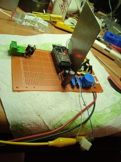
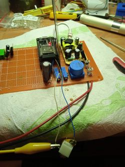
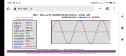
    Analyzer - meter of 230VAC network parameters - single phase. Analyzer - meter of 230VAC network parameters - single phase. Analyzer - meter of 230VAC network parameters - single phase. Analyzer - meter of 230VAC network parameters - single phase. Analyzer - meter of 230VAC network parameters - single phase. Analyzer - meter of 230VAC network parameters - single phase. Analyzer - meter of 230VAC network parameters - single phase.
    @futek2 Nice thing, I calibrated with a fan heater, it took some 8.4A according to the Soviet lean meter. Graphs received by phone in ESP mode as AP. I still need to build it, which will probably take me a long time. When the input of the current transformer is shorted, you can see garbage on the current diagram, is it normal or is there some disturbed environment in my place? I tried to put a steel sheet (from Inpost's recommended ones) between the power supply and the processor, but it doesn't change anything. It seems to me that giving the current to 3 decimal places does not make sense. Personally, I'd be happy with one, but that's not important. When I build it, I will take it to the field, I have a plant where "capacitive power is given back" after hours, probably by computers and maybe overcompensated fluorescent lamps, I've always wanted to test it, but so far there was only a reactive power regulator with current measurement on one phase. Probably then he will be interested in collecting data for some server.
    Did you choose the 1000uF and 470uF capacitors specifically?
    However, I have a software order to put a link to the home page on each screen, because it seems to be possible to get anywhere from there and it's good to be able to go back.

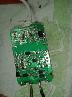
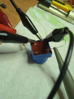
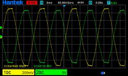
    By the way, I connected a voltage transformer to 12VAC and an oscilloscope and I don't really understand why my phase is reversed. Apparently, according to the documentation, the dots are in a line and so I have a common ground, and the phase is vice versa. How is it with this? The resistor in the power supply is 10k at the 470? output. From cursory calculations, it was over 1.2mA at the power supply and below 1.2mA at the output, but the difference is close to hundreds. And my oscilloscope is not a very accurate measuring device.

    If anyone wants such a power supply, it is at the Baker, number 39550 for PLN 10 net. It looks decent, has a fuse resistor, choke on the input and output. Stabilization without an optocoupler, but loaded with a small car bulb gives advice. And there is still a 2-core microusb cable after it.
  • #88
    futek2
    Level 19  
    Hello.
    Congratulations col jarekgol that everything is ok. !!!
    Another example that the meter is ok for such a small amount of money,
    This garbage is from ESP32 I struggled with it a bit but I gave it a rest as we are interested in larger currents when measuring network parameters, especially the power factor, which can be seen very nicely on the shift of sinusoids.

    As for the capacitors, I took as small a size as possible and a large capacitance.
    because they must win the voltage well so that they do not impose on the shape of the sinusoid of current and voltage.
    From what I see that you have a loosely assembled system for now, you can try to add 1000uF to it one more and be proud of the result, but I don't think it will change much.
    In the coming days, there will be another version of the software with corrections that colleagues have reported.
    I will also make a small correction with sending the results to the server, it is also a catchable error by my colleagues.
    And how did you upload the software to ESP32 using one of the programs I described recently?
    But overall the project works, and quite correctly.
    Once again col. jarekgol my words of appreciation that you built it and there was no problem with starting.
    Regards
    Futek2
  • #89
    jarekgol
    Level 31  
    I wonder if you would have a lot of work with making a typed configuration for different transformers (e.g. 5/25/100). I've seen these transformers in the 5A/1V version and they would be nice for viewing home appliances, and they sell this with a jack plug so they are easily interchangeable. I have planned a socket.
    If you want to fight, you can make a workaround that below some threshold of the measured current, it does not display the graph and does not take measurements ;) the threshold could also be in the config as a numerical field / tick.

    I really like the solution with measuring artificial mass :) Thanks to this, it does not have to be so stable.

    futek2 wrote:
    And how did you upload the software to ESP32 using one of the programs I described recently?

    I uploaded as described, first blink with Aurduino via Platformio, then your binary to the address 0x10000 with the command I use Linux on a daily basis and avoid Windows if I don't have to ;)