Elektroda.com
Elektroda.com
X

Analyzer - meter of 230VAC network parameters - single phase.

futek2 9183 114
This content has been translated flag-pl » flag-en View the original version here.
  • #91
    lukiiiii
    Level 29  
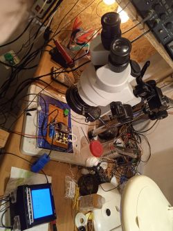
    I built it too.
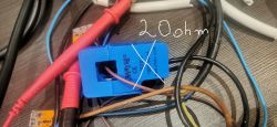
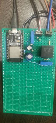
    I spent a week collecting the necessary parts. I had a current transformer from another unfinished project, but it was 100A 50mA, without a built-in resistor, you had to add a 20 ohm resistor in parallel to make it work.

    The voltage transformer is tv16E, supposedly more accurate, there was no delivery of the blue one in a reasonable time on the Polish auction site. :)
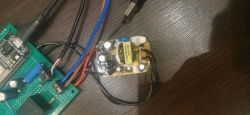
    5V 2A power supply pulled from some plug-in power supply.
    housing will be.

    The ESP32 board is the same as recommended by the author. I uploaded the batch with the ESP-Flasher-x86.exe program, which weighs 12M. It worked right away, I mean ESP without measuring.

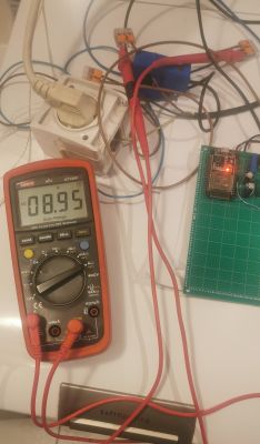
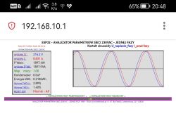
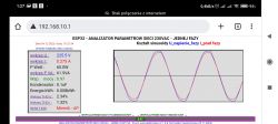
    After soldering on the universal plate (I will not boast about its bottom part :) ), the measurement was strange, the sine wave of the voltage was only in the negative part, and there was no current measurement at all. MY MISTAKE was not connecting the ESP ground leg with the rest of the system. After connecting and calibrating everything started.

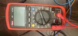
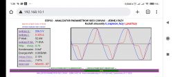
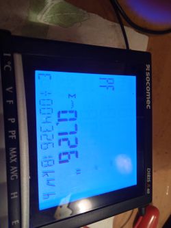
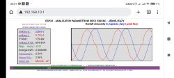
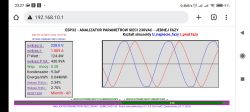
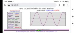
    I made the calibration on the dryer and the boiler, using the meter from the photo. :(

    I also managed to connect to my home router, not right away, I didn't read that you have to enter the server address to send these three characters, then it saves.

    You have to hurry a bit when logging in admin admin, because the page reloads.

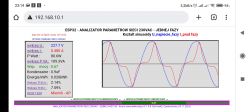
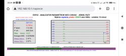
    The last photo shows the work of the laptop with the game AOE4 in the background. There are plans to connect the whole apartment (1 phase, pre-meter B40, accumulation stoves, boiler, induction hob).

    As for the reactive power, I have a constant flow of about 1A (measured with another device) from the induction hob on standby, I guess it is capacitive power, so far the ZE meter does not count it - I checked, but we live in interesting dynamic times and who knows when you will have to pay for it, someone will tell you whether companies are currently paying for power with capacity? The question is what to connect to eliminate it, some choke?


    As for the expansion of the system, it would be useful:
    - controlling the relays, as the author mentioned, from capacitors or switching on subsequent loads, according to, for example, the available contractual power, or the voltage approaching 253 for FV fans.
    - maybe controlling the hd44780 i2c lcd display with basic data
    There can be hundreds of ideas.
    Analyzer - meter of 230VAC network parameters - single phase. Analyzer - meter of 230VAC network parameters - single phase. Analyzer - meter of 230VAC network parameters - single phase. Analyzer - meter of 230VAC network parameters - single phase. Analyzer - meter of 230VAC network parameters - single phase. Analyzer - meter of 230VAC network parameters - single phase.
    Analyzer - meter of 230VAC network parameters - single phase.
  • #92
    jarekgol
    Level 33  
    Why in the screenshot from @lukiiiii the sinusoids are visibly shifted, and the factor is 1 (where there are nice graphs)?
    @futek2 Do you add some offset so that they don't overlap as there is a resistive load, or is something wrong? As I tested on a fan heater that has a motor, so I didn't go deeper and it showed 0.99, but here the peaks and zero crossings are shifted, and the coefficient is 1.00
    When I get to my hole, I will try to measure the farel motor itself on a resistor and an oscilloscope, because your meter already showed a "square" sine on a small consumption there.
  • #93
    futek2
    Level 19  
    Hello
    This slight offset of the sinusoids is due to the difference in the magnetic materials in the transformers. I do not want to correct it because I would have to change the current sampling time in relation to the voltage.
    But you can change it just reverse the current transformer and it will be correct
    It is corrected in the calculations of the power factor because it is counted on crossings through 0. U kol fukiiii is, I would say, perfect. Congratulations on making the meter. And the success that it worked without a problem and the calibration is also ok
    Colleagues, I think that if some comments are collected and some idea for improvement, the next version of the software will appear.
    Current latest 1.0.8.

    https://www.elektroda.pl/rtvforum/viewtopic.php?p=20300780#20300780

    The meter for such little money gives a lot compared to expensive company ones because maybe not many have access and if someone has it, maybe they could boast about the results of the comparison.
    Attached is a fragment of the invoice with the fee for inductive and capacitive reactive energy.
    It can be seen that there is something to fight for in a month, the meter pays off when you diagnose the place where this reactive energy is generated.

    Regards and good luck with your measurements.
    Futek2
  • #94
    jarekgol
    Level 33  
    futek2 wrote:
    It is corrected in the calculation of the power factor because it is counted at 0 crossings

    How do you calculate the ratio? Like manually on an oscilloscope or from a Fourier distribution?
  • #95
    futek2
    Level 19  
    Hello. In the first version of the program, I wrote my own counting algorithm. But after some time I found that it is free and I used the description I mentioned in the first post and used this solution

    https://github.com/openenergymonitor/EmonLib
    It works quickly and has a correction of this minimal shift on the factor of magnetic materials in the transformers.

    Having a rented company meter, the difference of COS fi is about 0.1, which is practically none, but it can also result from other ways of counting.
    But this link has not been updated for several years and it seems to be good and I can confirm that it works quickly, although I significantly increased the number of samples several times because ESP32 has a lot of computing power, I could afford it.

    Regards.
    Futek2
  • #96
    jarekgol
    Level 33  
    I'm asking because I'm very interested in measuring distorted waveforms, but I don't really have a rectifier at home that would take a few Amps. I was hoping, when I read about harmonics, that this is how it is calculated, but when I looked at the code from github (because I couldn't click on any "verbal" description) it doesn't look like that.
    If I conjure up a few amperes of distorted current from somewhere, I'll check it out.
    ps. how do you see the option for a 5A transformer?
  • #98
    metalMANiu
    Level 20  
    futek2 wrote:
    This shows that there is something to fight for in a month the meter returns

    It's true, there's something to fight for.
    It is puzzling that in the calculation the unit of inductive reactive energy is kWh.
    It's scary to think who the bills of millions of people depend on :)
  • #99
    jarekgol
    Level 33  
    @metalMANiu, perhaps only when it goes above zero, the right unit will jump in, but the fact looks bad. Another thing is that if they don't say how much it was, but only "over the contract" it's hard to determine where you are...
  • #100
    futek2
    Level 19  
    Hello.
    If you are interested in counting THD, I recommend reading this link
    It is not difficult because nicely described with examples friendly content for the average reader.

    https://www.elektroda.pl/rtvforum/topic3368455.html

    I used this description when writing the code for the analyzer, good cooperation with the author.

    A big thank you to the author of this description, Col.
    TechExpert and his quote

    The Furier transform is sometimes called Four yera because it sometimes takes 4 years of study to master it


    Regards.

    Futek2
  • #101
    khoam
    Level 42  
    There is a library available for ESP32 ESP-DSP in which FFT (Fast Fourier Transform) algorithms for float and fixed point numbers are ready. The code is largely written in xtensa assembler, well documented and with examples.
    link .
  • #102
    TechEkspert
    Editor
    Thank you :) when I find a moment, I will try to prepare a material about ESP and this library.
  • #104
    Dariusz Goliński
    Level 22  
    Well, that can happen at this pace of looking for money everywhere.
    The more so that the ECO fashion circle is constantly tightening.
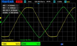
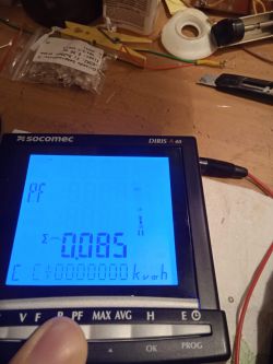
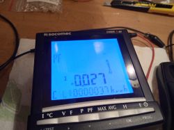
    LED lighting here and there, home automation from impulse power supplies, pseudo-intelligent houses, cause the amount of capacitive reactive energy to constantly increase.
    I have a friend who, wanting to save money and be ECO, installed LED lighting everywhere in her private school.
    The effect was that the cost of electricity came to her 15k - from yes.
  • #105
    futek2
    Level 19  
    You have to be vigilant as Fig.
    Because many see only the first page of factors and details of what we pay for are on the following pages. I have a few friends who already have bills after installing the heat pump, and the fee for reactive energy has already appeared, the same is true for air conditioners.
    The analyzer meter is very useful to me, I think that colleagues who built it also notice its usefulness.

    Regards
    Futek2
  • #106
    jarekgol
    Level 33  
    futek2 wrote:
    I have a few friends whose bills after installing the heat pump have jumped significantly and the fee for reactive energy has already appeared
    and say whether it is in plants or at ordinary consumers, and if the latter, do they have PV and a contract for the sale of electricity to the grid?

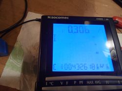
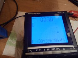
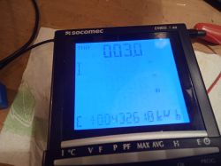
    Photos from the last tests of the 5A version and comparisons with the indications of Socomec Diris A40, connected without transformers, i.e. also 5A
    Two 100W bulbs in series, there under the shelf, on the socomec PF=0.999:
    Analyzer - meter of 230VAC network parameters - single phase. Analyzer - meter of 230VAC network parameters - single phase. Analyzer - meter of 230VAC network parameters - single phase. Analyzer - meter of 230VAC network parameters - single phase. Analyzer - meter of 230VAC network parameters - single phase.
    Computer (Dell C2D) probably with passive PFC
    Analyzer - meter of 230VAC network parameters - single phase. Analyzer - meter of 230VAC network parameters - single phase. Analyzer - meter of 230VAC network parameters - single phase.
    50uF capacitor, there seems to be a problem with the current graph (recorder mode) because on the left over 3A, and the graph goes along the bottom:
    Analyzer - meter of 230VAC network parameters - single phase. Analyzer - meter of 230VAC network parameters - single phase.
    Choke from the lamp 125W (6 ? ;)
    Analyzer - meter of 230VAC network parameters - single phase.
    and an oven (nothing interesting)
    Analyzer - meter of 230VAC network parameters - single phase.
    That night I finished at the second, today I still want to connect the choke and capacitor to the socomeca.
    By the way, the shape of the capacitor current is interesting, kind of wavy.

    @futek2 from my suggestions or wishful thinking:
    1) it would be good to move the "reset" link away from other clickers
    2) make some settings (interface + write in eeprom) where you can disable waiting for existing wifi
    3) As above with the 5/25/100 switching option, I mentioned earlier, let me know if it's real or if each transformer needs its own 800kB of code ;)
    4) the power factor after a load change "recovers" for several successive refreshes, each 5s. I would love to see options (also as user configurations) where PF is calculated and displayed from what is currently visible on the graph (sinusoid). I understand that it is unnecessary for a meter to collect totals over a long period of time, but for reporting phenomena on a desk it would be nice, and 5s is still a lot of periods for different averages.

    Regarding this article on the energy scanner, they write there that
    Quote:
    Most power grid operators in Poland set the power factor they tolerate within the range of 0.2-0.4. This means that for every 100 kWh of active power consumed, we can charge, without an ADDITIONAL fee, depending on the terms of the contract, from 20 to 40 kVar of inductive reactive energy.

    and my experience shows that yes 0.4, but tangent ? which translates to cosine 0.928, i.e. 7.2kVar for these 100kW
    https://www.naukowiec.org/przelicznik-katow.html
  • #107
    futek2
    Level 19  
    Hello Col. jarekgol
    Congratulations on making the meter. I wish you enjoy using it.
    And the measurement results to be helpful in improving electricity receivers.

    If I find some time, I will correct this error with calculating the current to the graph, because I think the conversion factor from 25A has been left
    As for the rest of the proposals, it does not provide for complicating the meter. My assumption was that it was supposed to be simple so that anyone interested could do it. And as for the various current sensors, they are not repeatable elements and therefore they are cheap. So that there is no problem with calibrating the meter. Because those from the upper shelf are expensive.
    So I am slowly closing the project and it does not provide for development, only the correction of noticed errors.
    Maybe someone will try to make a better design.

    Finally, information that if the meter is in AP mode, you do not need to enter the IP address from the browser, just enter it. ESP32.local same when connected to home router.

    Regards.
    Futek2.
  • #108
    lukiiiii
    Level 29  
    Can I ask for a pathological description of the shipment at https://thingspeak.com/

    I have an account but it's not sending, In the API KEYS field I entered Write API Key and the address is api.thingspeak.com
    I feel in my bones that I'm doing something wrong.
  • #109
    jarekgol
    Level 33  
    I have comparisons for choke and capacitor. The differences in PF are large, moreover, a common sense factor of 0.3 given by your meter is something not very. The oscilloscope measurement (counting the zero crossings) for the choke coincides with what the socomec shows.
    We are talking about differences of 0.3 vs 0.085 and 0.21 vs 0.027
    Choke:
    Analyzer - meter of 230VAC network parameters - single phase. Analyzer - meter of 230VAC network parameters - single phase.
    Analyzer - meter of 230VAC network parameters - single phase.
    Capacitor:
    Analyzer - meter of 230VAC network parameters - single phase.
  • #110
    futek2
    Level 19  
    Col jarekgol
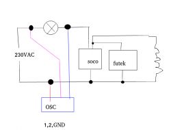
    Are you sure you connected the meters correctly? Because according to the diagram you showed, it is wrong because the current and voltage sensors are always to be on the power side before the load.
    Maybe change the direction of the current sensor fastening because it may also overlap.
    I think you have a manual for the meter, this is a connection diagram and I suggest you check it because the differences are very large. I did the trials and the differences are almost none.
    Regards
    Futek2
  • #111
    jarekgol
    Level 33  
    If I change the direction of your transformer, it shows that it does not like the direction of energy flow, and in socomec, if it is the other way around, the power of the bulbs shows negative. That's not it either.
    I've looked through the thread now and there are actually no screenshots of measuring simple elements anywhere. As someone has already thrown something, these are elements with complex consumption (the engine always takes a little bit of this, a little bit of that) so it's hard to say how good the measurement is and whether the error does not grow close to zero.
    @futek you wrote that you made 45uF, connect such a capacitor to your meter and post it here when it comes out, and I did the 5A version. For light bulbs, it shows reasonably, so there should be no hidden or undercalibrated shifts.
  • #113
    SAWEK101
    Level 31  
    Hello, my friend Futek 2 aptly mentioned that the connection diagram you provided will just curve the reactive power, so check if you really connected it, because if you power the meter after the transformer, you clutter the reactive power reading at low power.
    Besides, I have an industrial meter of this type at my connection, only a Chinese one and I will say that with low power of 100W, the accuracy is poor, I think it will be similar here because this is not the intended range of its operation, even though the transformer is selected for 25A.

    I came here because I would like to somehow send production data from old inverters to pvmonitor, I wasn't interested in ESP and it's beyond me in terms of software, I thought about fighting with sending via rs232 but I think such a counter would be a better option.
  • #114
    lukaszd82
    Level 30  
    Hello,
    I have a request for the author.
    Is it possible to prepare a code for the SCT013 transformer with a range other than 25 and 100A.
    100A is too much for me, while due to various perturbations on the markets, 25A transformers are becoming rarer. It is enough to look at the websites of our slant-eyed friends to see that they currently offer the transformer mainly in the 5-10-15-20-30-50-60-100A/1V versions
    The 25A version is a rarity (I don't really know why) and hence its price is constantly going up.
    It seems to me that preparing the code for version 20A would be a good idea :)
    Regards
  • #115
    futek2
    Level 19  
    Hello buddy lukaszd82 .
    You say, and you have.
    I made the version as you suggested with a range of 20A, These 20A * is the calibration range, but on the graphs the scale is up to 25A because I know from experience that these transducers can carry out measurements with an excess. I added an asterisk to make it clear that this is a calibration point.
    Soft attached with a description that it is up to 20A.
    In addition, a program for uploading software (BIN file) to ESP32 and ESP8266, two versions for 32 and 64 systems.

    Please provide any comments.

    The scheme has not changed and all functions are preserved as in versions for other ranges.

    Regards and I wish you satisfaction with the used meter.

    Futek2