logo elektroda
logo elektroda
X
logo elektroda

Analyzer - meter of 230VAC network parameters - single phase.

futek2 15600 129
ADVERTISEMENT
Treść została przetłumaczona polish » english Zobacz oryginalną wersję tematu
  • #31 20258230
    khoam
    Level 42  
    futek2 wrote:
    But no one has yet made this measure, so there is no topic to discuss the results of the measurements.

    Probably won't. As I wrote to you on PW: if you used a LUT for calibration, then on another ESP32 you need to regenerate this table and compile the code, and for this you need sources. Tests without ADC calibration in ESP32 are a bit meaningless.
  • ADVERTISEMENT
  • #32 20258259
    futek2
    Level 19  
    Hello
    Once again, I inform you that calibration is only necessary with potentiometers because I chose the middle of the ADC range to make it easier to make the meter and calibrating the voltage to rather large deviations does not matter because everywhere is about 230VAC and the current calibration is similar. And the main calculation is the power factor, and this is calculated at the times the sine wave goes through 0.
    The tests performed with different versions of the software gave an error of about 1.5%. This is not a 0.5 class meter. And by providing the description of the meter, my intention was to get to know how our equipment generate harmonics and unfavorable power factor, for which we pay more for electricity.
    And these parameters will not be measured with typical meters, nor will we be able to see what is happening in our home electrical installation.
    I am convinced that there will be colleagues who boast of their graphs of what is happening in their home electrical network and those who have PV installations how it affects the network.
    I wish the charts were like books.
    Regards
    Futek2
  • ADVERTISEMENT
  • #33 20258443
    Dariusz Goliński
    Level 22  
    And you can get an energy meter.
    I wanted to compare the operation of devices in a daily cycle with the changed parameters.
    I already have some ideas where to use it.
  • #34 20258502
    futek2
    Level 19  
    Hello Col. Darius Golinski
    You say, and you have.
    There is energy counting.
    In that smaller window on the left.
    But I did not manage to test for a long time how accurate the kWh calculation is
    But if something is wrong, please let me know and I'll send you a fix. Theoretically, it should be fine.
    Regards
    Futek2
  • #35 20259008
    Dariusz Goliński
    Level 22  
    Thanks.
    And great. He's picking up toys next week.
    I just have a question. Could this power input be recorded over time?
    I mean, for example: I have a control cabinet air conditioner. And I would like to know what power this air conditioner will consume for 24 hours when it will have a set temperature of 16 C and how much at 26 C, for example.
  • #36 20259076
    futek2
    Level 19  
    Hello.
    Before you buy the necessary parts, I will ask you to make it possible to connect the meter to your home router and send measurement data to the server to collect them there and draw a graph. I've already tested it and it works. Sending would be:
    Voltage, current, power VA and COS fi and energy in kWh. And the fact that the kWh energy will be an incremental graph and it would be advisable to think about configuring the graph on the server to, for example, draw it in the form of a bar for each day.
    Because it would be pointless to manually reset the meter once a day to reset the kWh counter
    Practice creating an account at https://thingspeak.com/.
    Sending data every 15 seconds because such requirements not more often. But it's enough for such needs.
    Regards
    Futek2
  • ADVERTISEMENT
  • #37 20259281
    Dariusz Goliński
    Level 22  
    Account created.
    I was thinking to increment some variable locally and display it on the page.
    There's a reset button underneath. (This is in case there is no internet access at the measurement site)
  • #38 20261095
    futek2
    Level 19  
    Hello, interested in the topic of the analyzer - meter of 230V single-phase network parameters.
    Attached is another version of the software for measuring current up to 25A and 100A.
    The attached version has web configuration options as shown in the attached picture.
    To run the config page, you must be connected to the meter's AP and make a connection from your browser
    192.168.10.1/config
    A login window will appear yes yes when updating the software; user; admin password; admin
    After successfully logging in, a window for entering configuration data will appear - the picture is attached.
    I think that it does not need to be described so that we have only 4 windows to provide data.
    In the home router router windows, it is understandable that
    In the eyes, the server to which the data for the charts will be sent is the default one api.thingspeak.com but you must fill in the field and enter the received user code.
    If someone does not want to send data, it is enough to enter 3 characters in the windows regarding the server and it will accept the configuration but there will be no data sending. This can always be changed in the next configuration.
    After saving the configuration, the meter after restart will establish a connection with the home router and the AP mode will no longer be active.
    If incorrect data have been given to log in to our home router, then after restarting the meter will restart in AP mode with the address 192.168.10.1 and we can perform the configuration again.
    Attached is a picture of how to configure the user account on the server so that the data sent plots graphs.

    People who have already uploaded an earlier version of the ESP32 firmware can update via the website 192.168.10.1/new

    Operation of the meter in AP mode allows you to use the meter normally but only within its WIFI range with all measurement functions.

    Please provide comments and suggestions for changes.
    Regards and I wish you a positive use of the meter.

    Futek2
  • #39 20261152
    -=Mario=-
    Level 12  
    Cool design.
    Maybe out of curiosity I will be tempted to put together and compare the measurements with the original recorder.

    Just a little suggestion.
    Since the current transformer is with a jack plug, you can make a universal soft for a 25A and 100A transformer.
    For example, you can use a processor input and a switch or software configuration.
    Of course, calibrations should be independently saved for both transformers.
  • #40 20261226
    futek2
    Level 19  
    Hello.
    I had such a thought at the beginning to make a switch in the palisade. But uploading new software takes a minute without the need to remove the ESP32 from the meter because you can upload the soft via the website by adding to the address /new and logging in and indicating the bin file and a moment and there is a new soft. I will remind you to buy a current transformer with a 1V output because it just fits in the range of the linear scale of measurements with the smallest error.
    The voltage transformer has a 1:1 ratio and additional resistors should be used to lower the voltage as if a resistance divider were used, but since we use a voltage transformer, we have full isolation from the network and we do not risk damaging the analog inputs in ESP32.

    I'm curious how the comparison with the factory meter will turn out. My comparison with the company meter went well. But it's never too much to know how it turned out.
    Regards.
    Futek2
  • #41 20261949
    burur
    Level 22  
    Interesting project.
    The graph on thingspeak with energy in kWh should not be incremental - "step"?
  • #42 20262317
    futek2
    Level 19  
    Hello
    Referring to thingspeak, if time allows, I will write a script that will show several graphs in one window and you will be able to see the dependencies. And the energy will be counted from zero every day. Unless one of my colleagues has more free time and would like to write such a script with comments indicating the place of changes to make it universal because I would like to write it.
    At the moment, there are no plans to change the meter's program code. Because so far colleagues do not report errors noticed.
    One of my remarks that the 25A and 100A versions are visually the same and the only difference is a different conversion factor for the current measurement indications.
    Regards.
    Futek2
  • #43 20269390
    futek2
    Level 19  
    Hello, interested in the meter - analyzer of 230VAC network parameters - single phase.

    Enclosed is another version improved with the option of recognizing the correct fastening of the current measurement sensor on the phase conductor.
    The message appears on the website below the table with the measurement results

    Minor errors in the appearance are also corrected, while maintaining all the existing options.
    Attached are two versions of the software for 25A and 100A.
    The software update can be done via the website after connecting via WIFI as described earlier.

    After updating the software, the configuration parameters are preserved, so the meter will connect to our home router.


    It is important to buy a converter
    current, please choose the type that has a 1V output


    Attached is the program for the first firmware upload to ESP32.
    Regards and I wish you satisfaction with using the meter.

    Futek2
  • #44 20269430
    exlibris71
    Level 17  
    I wonder why two versions of the software (for 25A and 100A) and not one more configuration option? Are there any contraindications?
  • #45 20269601
    futek2
    Level 19  
    Hello.
    Corresponding to col. exlibris71.
    There is a problem with current measurement sensors, they are not of the highest quality and there are differences, and after assembling the meter, you should calibrate the current measurement for a given sensor using a digital meter and load the circuit at least to 75% of the measuring range, and then set the current value indicated by the ammeter with a precision potentiometer. we do the same for the voltage measurement range. But we set the voltage to the value indicated by the voltmeter. Voltage changes are in a small range and it does not have a major impact on the result of COS fi or THD calculations.
    The power factor result and THD are calculated by detecting the current and voltage sine wave crossing 0 and converted to phase angle differences and similar is the case with THD. The only thing that after calculation is the capacitance of the capacitor depends on the value of the current and voltage because there must be compensation of the inductive reactive power in KVAR, it requires the selection of the approximate capacitance of the capacitor. The sensor used to measure the current is about PLN 25 and when testing different ones, they required correction with a precision potentiometer after replacement. I could not make the soft to be dedicated as a universal one because despite the fact that the construction of the meter is simple, the accuracy of the measurements is achieved by calibrating with a precision potentiometer.
    Measurements are made every 4 seconds and the sampling time every 0.2ms in each cycle is 4000 samples and in the case of THD measurement there are 2048 samples must be a multiple of 2. As you can see, the graphs are smooth. The voltage and current sine wave graphs are automatically scalable to fill the maximum plot area so that the offsets and shape can be clearly seen. And the exact values are calculated in the window on the right side of the website.
    I think that this solution allows you to make a meter for every budget, even for a novice constructor, using cheap elements that are of good quality and generally available on a well-known auction site.
    The use of transformers makes the meter completely isolated from the mains during measurements and is safe for the user.
    I think that colleagues who decided to make a meter share their comments and photos of the measurements made and their comparison with a digital meter.
    Attached are a few photos of how I managed to compensate for inductive reactive power in my house. At present, it is enough for a small-capacity capacitor to be used in fluorescent lamps with a choke as in the past.

    The THD coefficient of the harmonic content has also decreased significantly.


    It is important to buy a converter
    current, please choose the type that has a 1V output


    Regards and I wish you satisfaction with using the meter
    Futek2
  • #46 20273667
    futek2
    Level 19  
    Hello, interested in the topic of the meter of network parameters 230 - single phase.
    A lot of discussion and none of the colleagues have yet made a meter to boast of their design.


    It's important to buy a converter
    current, please choose the type that has a 1V output


    Colleagues, it's time to brag.
    Futek2
  • #47 20280728
    futek2
    Level 19  
    Hello, interested in the meter - analyzer of 230VAC network parameters - single phase.

    Enclosed is another version improved with the option of plotting the voltage, current and COS fi graphs for the last 15 minutes without the need to send data to the server.
    Just click in the place indicated in the attached image and a page with real-time charts opens

    Minor errors in the appearance are also corrected, while maintaining all the existing options.
    Attached are two versions of the software for 25A and 100A.
    The software update can be done via the website after connecting via WIFI as described earlier.

    After updating the software, the configuration parameters are preserved, so the meter will connect to our home router.


    An important thing to want to build a meter is to choose a transformer
    current type, which has a 1V output - it is marked on the transformer.

    As a reminder of the layout, I attach the diagrams of the meter.
    Attached is the program for the first firmware upload to ESP32.

    Regards and I wish you satisfaction with using the meter.

    Futek2
  • #48 20288917
    Sentymentalny
    Level 14  
    Did you manage to find some time and take measurements for "I plan to do similar tests with other engines such as from the central heating circulation pump or an automatic washing machine and even a refrigerator." ?
    I am very interested in such an analysis.
  • #49 20288939
    futek2
    Level 19  
    Hello.
    I recently measured how the washing machine works.
    Chart attached. This is the version with last 15 minutes of logging
    It turned out interesting. Picture attached.
    How to connect a capacitor?
    Because the motor in the washing machine has several modes of operation
    And I'm thinking to make a single-phase transmittable reactive power compensator based on this meter because ESP32 does not use outputs and it would be possible to control the receiving of capacitors.
    Kota has already done something like this because on the web I found a diagram from years ago but on ARDUINO which is attached.
    Regards
    Futek2
  • #50 20289111
    Sentymentalny
    Level 14  
    And is there an analysis of the operation of the refrigerator unit in the near future?
    In an apartment in a block of flats, the fridge is usually the biggest source of energy consumption.
  • #51 20289755
    jarekgol
    Level 39  
    Can your system run on a D1 board (esp wifi?) I have no experience with ESP, but I have one at home.
  • #52 20289784
    futek2
    Level 19  
    It should only be possible to check if the soft will work after uploading, but the processor must be ESP32. And a memory of at least 1MB because the bin code is about 800kB
    I don't know what the numbering will be like.
    I don't have this type of plate, but maybe one of my colleagues will tell you something more. I can change the pin numbers in the code that will correspond to your board and make compilations
    Regards
    Futek2
  • #53 20289807
    jarekgol
    Level 39  
    I have this https://en.wikipedia.org/wiki/ESP8266 it says that 32bit and 1MB flash, but it is also written that the successor of these processors is the ESP32 series. So if I understand you correctly - no?
    Anyway, I ordered the converters, I will also buy the board somewhere and we'll see :)
  • #54 20289856
    futek2
    Level 19  
    The problem with using ESP8266 because you have one is that it has only one ADC input. And three inputs are needed. One for reference voltage measurement, one for voltage measurement and one for current measurement. And ESP 32 has a lot of them, as many as 10. Except that not all of them can be used as WIFI is used in the program. But that's enough of them.
    As I recently bought ESP32 on a well-known auction site for PLN 25 and they are probably still available.
    Regards
    Futek2
  • ADVERTISEMENT
  • #55 20289867
    jarekgol
    Level 39  
    I get it, I also found these after 25, I ordered :) How to upload the software for the first time? Because I used mine as Arduino via Platformio, but then I compiled the sources myself and it continued to upload "on its own".
  • #56 20290139
    futek2
    Level 19  
    Attached you have the program to download for the first time.
    Uploaded from address 00000.

    Simple to use.
    Then you practice on the web, it's even faster.
    But there is no need to remove the module from the meter. This solution of software update via www is practically used in all my projects and works reliably.

    You can do it.
    Regards
    Futek2
  • #57 20291628
    Dariusz Goliński
    Level 22  
    Something flasher can't connect to my board. Will try tomorrow on another computer.
    Is it normal that the ESP32 can is warm?
  • #58 20291803
    futek2
    Level 19  
    Hello
    If you only connected the ESP32 with a USB cable, the red LED will definitely light up. There is no need for a separate power supply when connected via a USB cable. Is the heat slightly noticeable, but it's not a high temperature. And what is simply a matter for the program to connect with the board, when it starts sending to the indicated port, you have to press the FLASH button for about 3 seconds and when it starts to upload, you slow down and wait until the upload is finished. It is recommended to turn off the power supply for a short time and when it starts, it should be ok and the blue LED will blink. And you can already connect to ESP32 via WIFI according to descriptions and pictures.
    I'm sure you'll get it all.
    Please be proud of how it went.
    Regards
    Futek2
  • #60 20292724
    futek2
    Level 19  
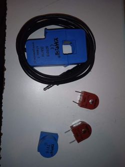
    These two transformers in brown brine are good for permanent threading of the wire because they are not opened.
    I wish you a quick launch of the analyzer.
    Regards
    Futek2

Topic summary

The discussion revolves around the construction of a single-phase 230VAC network parameter analyzer using an ESP32 module. Key components include the ESP32 DEVKIT V1, current transformers (SCT013 for 25A and 100A), and a voltage transformer (TV16). Participants share insights on measurement accuracy, calibration methods, and potential improvements, such as adding energy counting features and enhancing data visualization. The author, Futek2, provides updates on software versions, calibration techniques, and the importance of using appropriate transformers for accurate readings. Users express interest in testing the device with various appliances and suggest modifications for better performance.
Summary generated by the language model.
ADVERTISEMENT