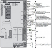
Hey, that's the situation:
- BFT Thalia light gate control panel to be controlled/read by Shelly Uni
- The control panel output for accessories gives 29V AC (it should be 24V AC ). This is unfortunately too much for Shelly, so I connected it via a separate 12V power supply DC . So I have AC on the control panel and DC on Shelly. Controlling the switchboard with this current works for me, worse with reading the switchboard --> Shelly
- the control panel on ports 20/21 gives power to the warning light - current flows when the gate leaves move; this is the aforementioned 29VAC accessory current
- I would like to detect this current with a binary sensor from Shelly; this is (I think) a "reed sensor", its designation is IN_1 or IN_2 (there are 2 such sensors): consists of a single connection to the circuit, which should detect a binary state of 0 or 1
- Unfortunately, my Shelly powered by 12VDC, does not detect 29VAC. My guess is that it can only detect the current it is supplied with (does this make sense?).
- so I came up with the idea of inserting a relay between ports 20/21 and the Shelly, which would switch on from 29VAC, while on power/transmission it would have 12VDC, which I would take from "my" 12VDC power supply (and switching would be from the control panel)
With a standard 5 pin relay it would look like this:
85 and 86 - 29VAC from the control panel
30 - "plus" from the 12VDC supply
87 - diode and to the 'minus' of the 12VDC supply, and somewhere in there attached sensor IN_1 from Shelly
Does this make sense and a request for a suitable relay. The currents are small: AC is 5W max, and DC as much as the diode. Or alternatively, how else to embrace this. Below are the schematics.


