logo elektroda
logo elektroda
X
logo elektroda

[Solved] Remote control of tactile switches in a staircase-crossing arrangement

raspberry_pajac 1851 15
ADVERTISEMENT
Treść została przetłumaczona polish » english Zobacz oryginalną wersję tematu
  • #1 18427296
    raspberry_pajac
    Level 6  
    Hello!

    I am in the final stages of finishing the flat. The lighting on the electrical side has been implemented in the traditional way – on mechanical switches, in places in stair and stair-cross arrangements. At the last minute, however, I began to lean towards installing touch switches, and specifically fell for Touchme (albeit not yet the final choice).

    First and foremost, I want to be able to control all the lighting remotely (via Wi-Fi), so I had planned from the start to use aftermarket relays like Shelly 1 (for single) / Shelly 2.5 (for double). However, the Touchme range offers switches with built-in Wi-Fi control, so this simplifies things considerably. Unfortunately, the exception to this is their touchme staircase and cross-over switches, where remote control would have to be realised in-house.

    Here you can find sample wiring diagrams provided by the manufacturer.

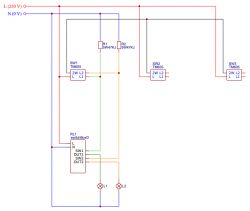
    Below is my output circuit – Touchme connectors successfully control the consumer (energy saving bulb 12 W):
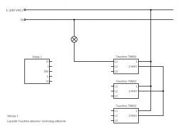
    Remote control of tactile switches in a staircase-crossing arrangement .

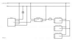
    I had assumed that the connection of such a coupler to a Shelly should not be particularly different from the connection to an ordinary mechanical coupler. Unfortunately – I was wrong. Below is my first attempt. The result: the Touchme connectors are not active because, I conclude, they do not detect the load.
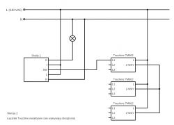
    Remote control of tactile switches in a staircase-crossing arrangement .

    I concluded that adding a parallel load should solve the problem. I decided on a 15 kΩ resistor (5 W). And indeed – the touchme switches became active again and the L1 output of the first one again showed a phase as a result of switching. Unfortunately, however, there was a lack of agreement between Touchme and Shelly, which was detecting a high state at the SW input all the time. Because of this, regardless of the state of the switches, the light was continuously on.
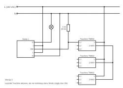
    Remote control of tactile switches in a staircase-crossing arrangement .

    I should add that I verified the operation of the Shelly relay itself – by connecting and disconnecting the phase to the SW input, the light turned on and off accordingly. The Shelly configuration is also appropriate – mode toggle switch . Additionally, I have several copies and each has behaved in the same way.

    My conclusion is that in the off state, the Touchme switches do not completely cut off their outputs (L1, L2 and L3), but current can still flow through them, which I guess is used for load sensing.

    Would anyone have any ideas on how to solve this problem? Perhaps use other Wi-Fi controlled relays? Or maybe insert an additional, ordinary relay between Touchme and Shelly or somehow filter the L1 output of the Touchme connector?

    I would only ask that you take into account the rather limited space of the boxes. Although, at my request, additional boxes have been made next to the boxes for the stair and cross connectors, exclusively for the remote control elements, but their capacity is small.

    I would be very grateful for any suggestions and help.
  • ADVERTISEMENT
  • #2 18427412
    daroka14
    Level 26  
    raspberry_pajac wrote:
    only further current can flow through them
    current does not flow but the voltage at the output is greater than 0. The easiest way is to insert a resistor between the switch and the relay but this has its drawbacks. A better solution is a triac but that's more space. A mechanical relay would also be ok but that's even more space.
  • ADVERTISEMENT
  • #3 18427522
    retrofood
    VIP Meritorious for electroda.pl
    raspberry_pajac wrote:
    At the last moment, however, I have started to lean towards fitting touch switches,
    .
    First and fundamental question. How do you have your electrical installation done, traditional or bushingless? Have you run N and PE wires to all switch boxes?
  • #4 18427566
    raspberry_pajac
    Level 6  
    Thanks for your answers!

    daroka14 wrote:
    The easiest way is to insert a resistor between the switch and the relay but this has its drawbacks.
    .
    Would you go for one with a very high resistance? What would be the disadvantages of such a solution?

    daroka14 wrote:
    A better solution is a triac but that's more space.

    Would you mean the triac (or optotriac?) alone or the whole circuit with the triac? Maybe an AC controlled SSR relay like the one below?
    Remote control of tactile switches in a staircase-crossing arrangement .

    retrofood wrote:
    First and fundamental question. How do you have your electrical wiring done, traditional or conduitless? Have you run N and PE wires to all the breaker boxes?
    .
    This is a traditional installation with junction boxes. N and PE conductors are led to the switch boxes. However, I also have access to the phase of the lighting circuit – I was planning to realise the control there.

    Incidentally, I made a few more measurements (layout as in the third diagram from the previous post):
    1) voltage between the SW input of the Shelly and the neutral wire = about 130 V (after disconnecting the wire from the L1 output of the Touchme switch),
    2) current from L1 Touchme output to SW Shelly input = approx. 1 mA (switch off ),
    3) current from L1 Touchme output to SW Shelly input = 0 (switch on ).
  • #5 18427602
    daroka14
    Level 26  
    raspberry_pajac wrote:
    Would this be one with very high resistance? What would be the disadvantages of such a solution?
    you would have to experiment, I would start with such a row of a few K ending with a row of a few M. In your case, maybe there will be no power loss because there is no operating current flowing through this wire, so a loss of a few pennies on the electricity bill per year. This is where you can start, the least expensive and easiest to do.

    Added after 2 [minutes]:

    raspberry_pajac wrote:
    Would you mean the triac (or optotriac?) alone or the whole circuit with the triac? Maybe an AC controlled SSR relay like below?
    triac + capacitor +coil and maybe some resistor. Ssr would be ok too, at this voltage it's just a circuit on a triac in a compact case.
  • ADVERTISEMENT
  • #6 18427716
    raspberry_pajac
    Level 6  
    daroka14 wrote:
    you would have to experiment, I would start with such a row of a few K ending with a row of a few M.
    .
    I have tested so far ranks of ceramic resistors (up to 5 W) with equivalent resistance from 1.5 kΩ to 39 kΩ – unfortunately still the same effect. I still have some resistors with higher resistance – these are ordinary THT resistors, up to 0.25 W or 0.5 W power. But at 230 V such a 1 MΩ resistor would only have a power of the order of 0.05 W, so it should be enough – am I understanding correctly?

    daroka14 wrote:
    triac + capacitor + coil and maybe some resistor. Ssr would also be ok; at this voltage this is the circuit on the triac in a compact case.
    .
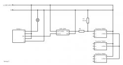
    Is my way of connecting (version 4) such an SSR correct? Or do it as in the diagram below (version 5)? How then to select the resistance of resistor R2?
    Remote control of tactile switches in a staircase-crossing arrangement
  • Helpful post
    #7 18427791
    daroka14
    Level 26  
    raspberry_pajac wrote:
    But at 230 volts such a 1 MΩ resistor would only have a power of the order of 0.05 W, so it should be enough – am I understanding correctly?
    enough.

    Added after 1 [minute]:

    raspberry_pajac wrote:
    Can it do as in the diagram below (version 5)? How then to select the resistance of resistor R2?
    It depends what input voltage range this ssr has
  • #8 18428906
    raspberry_pajac
    Level 6  
    raspberry_pajac wrote:
    I still have some resistors with higher resistance
    .
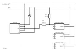
    I have checked resistors up to 105 MΩ – unfortunately with the same result. Maybe I am doing it the wrong way? Below is the diagram (version 6):
    Remote control of tactile switches in a staircase-crossing arrangement .

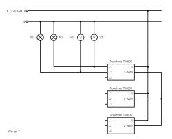
    I did some more voltage measurements with the Touchme switches themselves, as in the diagram below (version 7). This time the switches are double (instead of single), but this does not affect the presence of the control problem via Shelly.
    Remote control of tactile switches in a staircase-crossing arrangement .

    .
    . 21eb9.
    21eb9
    21eb9c9
    d6a6
    State L1 State L2 V1 [V] . V2 [V]
    on on 235 235
    on off 235 4
    off on off 24 235
    off off 6 6
    .

    Can anything be deduced from the above results? In addition, there remains the question of the measured 130 volts between the bare SW Shelly input and the neutral wire.
  • #9 18434249
    YR1
    Level 24  
    I'm not sure if they should be this type of module and this manufacturer. I remember fitting something like this last year. Some of the functions worked, some did not. It turned out that you had to download a PAID application to configure the circuit. I remember that the product was PL, had a lot of expandability. Similar to KNX, however it did not work over "cables" like KNX or DALI but over WiFi.
    Consult the manufacturer, I did so and only then found out about the application. There was nothing about it in the manual.

    Added after 6 [minutes]: .

    YR1 wrote:
    I'm not sure if they should be this type of module and this manufacturer. I remember fitting something like this last year. Some of the functions worked, some did not. It turned out that you had to download a PAID application to configure the circuit. I remember that the product was PL, had a lot of expandability. Similar to KNX, however it did not work over "cables" like KNX or DALI but over WiFi.
    Consult the manufacturer, I did so and only then found out about the application. There was nothing about it in the instructions.
    .

    Correction. It concerned the FIBARO products
  • ADVERTISEMENT
  • #10 18434286
    daroka14
    Level 26  
    raspberry_pajac wrote:
    Additionally, there remains the issue of the measured 130 volts between the bare SW Shelly input and ground.
    When you say ground do you mean N or PE?
  • #11 18434363
    raspberry_pajac
    Level 6  
    daroka14 wrote:
    when you say ground you mean N or PE?
    .
    Fact – I was using the incorrect nomenclature. I have already corrected it. I meant the neutral wire.

    YR1 wrote:
    Consult the manufacturer, I did so and only then found out about the application. There was nothing about it in the instructions.
    .
    Thanks for the tip, but unfortunately I have already contacted the manufacturer and he was unable to give me advice on how to solve this type of situation. There is indeed an app, but exactly the Touchme staircase switches do not have Wi-Fi connectivity at all (hence, incidentally, my attempt to uintelligent them using Shelly).

    In the meantime, I have further established that intelligent connectors are divided into:
    • those that require a neutral wire (with these a similar problem would probably not exist) and
    • ones that do not require a neutral wire (such as just e.g. Touchme), they connect in series with the receiver and are powered via exhaust current – hence the stricter requirements on the minimum power of the connected receivers and the possibility of buying special adapters topping up the circuit.
  • Helpful post
    #12 18434497
    daroka14
    Level 26  
    raspberry_pajac wrote:
    Scheme below (version 6):
    .
    have you tried connecting with this schematic? 15 kohm is not enough. Try putting 3-10mohm there and between the switch and relay with 100k. Doesn't it work either? Measure the resistance between SW and N or O on the relay. Make the equivalent resistance between the switch and the relay bigger than the one between the output of the switch and N. Just beware, in this relay there may be a semiconductor element whose resistance is close to infinity and only the applied voltage changes this, then it is best to measure the current, voltage and calculate from Ohm's law. Any wonder you are having such problems with it.

    Added after 7 [minutes]: .

    raspberry_pajac wrote:
    Fact – I was using incorrect nomenclature. I have already corrected it. I meant the neutral wire.
    measure between sw and PE.
  • #13 18434522
    raspberry_pajac
    Level 6  
    daroka14 wrote:
    tried connecting with this diagram?
    .
    Yes, the effect was unfortunately the same – Shelly continued to detect a high state for any switch state. As resistance R2 between the switch and the relay, I checked the values starting at 1M and ending at 105M (I connected the resistors I had in series) – no change. Resistor R1 (15k; between the switch and the neutral wire) was only for the power supply to the switches.

    I will try to take additional measurements today when I am on site.
  • Helpful post
    #14 18436935
    daroka14
    Level 26  
    Try connecting one relay via a triac preferably according to the diagram from Wikipedia only without that 1.5 M resistor and potentiometer. Maybe this will work because with these resistors probably nothing will.
  • #15 18766462
    raspberry_pajac
    Level 6  
    I am back on topic after a long while. I decided to test the circuit still by replacing the Shelly with a Polish made switchBoxD .

    I connected using 5W47KJ resistors as shown in the diagram below:
    Remote control of tactile switches in a staircase-crossing arrangement .

    The result: it works. It is possible to switch both physically - with a switch - and via the web interface switchBoxD. I selected the 47k resistance by going down from 1M (0.25W), through 330k (0.25W), 100k (5W) and 57k (5W). Only at 47k did the switch detect the load and start to function.

    Previously, connecting via the LED adapter from Touchme also worked. A multimeter measurement indicated the resistance of such an adapter to be 15k (unplugged). As the adapters were getting quite hot, I also tried connecting 2 in series to the output and this also worked and the power was evenly distributed.

    Unfortunately, the 47k resistors get even hotter (they are also smaller in size than the adapters). My question is – would it be safe to enclose them in a can after all, along with the switchBoxD relay? The temperature of each measured with a kitchen thermometer is about 74°C 8-) Or would it be better to connect several in series again to spread the power?

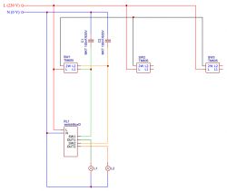
    Unless, instead of 5W resistors, to use something else, like MKT 100 nF / 630 V capacitors?

    Remote control of tactile switches in a staircase-crossing arrangement .
  • #16 18777764
    raspberry_pajac
    Level 6  
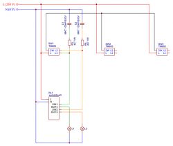
    I finally connected using MKT 100 nF capacitors (630 V), adding 4.7 kΩ (1 W) resistors in series for additional current limitation. It works stably and the heating problem is no longer present.

    Remote control of tactile switches in a staircase-crossing arrangement .

    I hope that the characteristics of the capacitors will allow continuous operation and that a reasonably constant impedance (at 50 Hz) can be assumed for them.

    Thanks for all the tips!

Topic summary

The discussion revolves around the implementation of remote control for tactile switches in a staircase-crossing arrangement, specifically using Touchme switches and Shelly relays. The author initially planned to use Shelly 1 and Shelly 2.5 for Wi-Fi control but faced challenges with Touchme's staircase and crossover switches, which lack built-in Wi-Fi. Various solutions were proposed, including the use of resistors, triacs, and solid-state relays (SSRs) to manage the control circuit. The author experimented with different resistor values and configurations, ultimately achieving functionality with a switchBoxD and specific resistor-capacitor combinations. The conversation highlights the importance of proper wiring and component selection to ensure reliable operation of the lighting system.
Summary generated by the language model.
ADVERTISEMENT