Hi
I am working on a project related to lock control (2). My solution will be based on esp32 an external application that will communicate with esp32. Based on the output, one of the two locks should open for a certain time.
I stress that I am green in matters of electronics hence I ask for your understanding
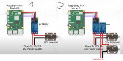
Below I paste the diagram (1 is the original for one lock and 2 is my idea for the extension to two locks).

I'm not sure if a second power supply is needed? Perhaps one is sufficient and the whole circuit can be simplified.
I am working on a project related to lock control (2). My solution will be based on esp32 an external application that will communicate with esp32. Based on the output, one of the two locks should open for a certain time.
I stress that I am green in matters of electronics hence I ask for your understanding
Below I paste the diagram (1 is the original for one lock and 2 is my idea for the extension to two locks).

I'm not sure if a second power supply is needed? Perhaps one is sufficient and the whole circuit can be simplified.


