logo elektroda
logo elektroda
X
logo elektroda

Convert 9W RGBCW Chinese Smart Bulb (WB2L Module) to 12V 1A RGB WiFi Strip Controller

serter34 2901 3
ADVERTISEMENT
  • #1 20552925
    serter34
    Level 2  
    Hello,
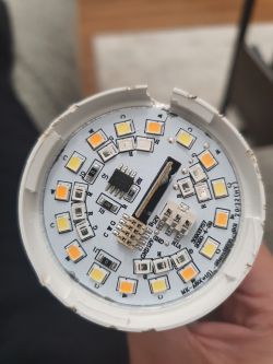
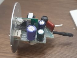
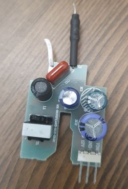
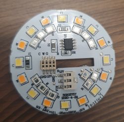
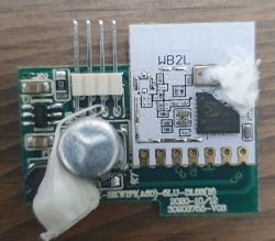
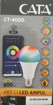
    My friend gave me a Chinese smart bulb (9w rgbcw) but I don't need 1 more bulb :) so I started to teardown. So this bulb uses WB2L Module.
    I really want to learn can I build my own rgb wifi controller from the bulb's circuit. I have a rgb strip lamp with an ir controller which uses 12v 1 amp.
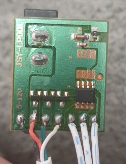
    So I tried to google circuit number etc but I couldn't find any diagram.
    Convert 9W RGBCW Chinese Smart Bulb (WB2L Module) to 12V 1A RGB WiFi Strip Controller Convert 9W RGBCW Chinese Smart Bulb (WB2L Module) to 12V 1A RGB WiFi Strip Controller Convert 9W RGBCW Chinese Smart Bulb (WB2L Module) to 12V 1A RGB WiFi Strip Controller Convert 9W RGBCW Chinese Smart Bulb (WB2L Module) to 12V 1A RGB WiFi Strip Controller Convert 9W RGBCW Chinese Smart Bulb (WB2L Module) to 12V 1A RGB WiFi Strip Controller Convert 9W RGBCW Chinese Smart Bulb (WB2L Module) to 12V 1A RGB WiFi Strip Controller Convert 9W RGBCW Chinese Smart Bulb (WB2L Module) to 12V 1A RGB WiFi Strip Controller
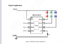
    So I think my rgb microcontroller is: https://datasheetspdf.com/pdf/1495890/BPS/BP1638CJ/1
    So basically I try to make a rgb controller with that little circuit.. so anyone can help me to convert this

    Ps ir controller; Convert 9W RGBCW Chinese Smart Bulb (WB2L Module) to 12V 1A RGB WiFi Strip Controller
    I know I could buy esp and make it but I wanna diy :) thanks for help
  • ADVERTISEMENT
  • #2 20553168
    p.kaczmarek2
    Moderator Smart Home
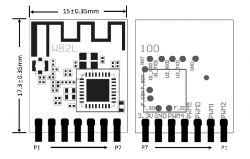
    Hello, here is WB2L pinout:
    Convert 9W RGBCW Chinese Smart Bulb (WB2L Module) to 12V 1A RGB WiFi Strip Controller
    As you can see, there are multiple PWM pins that you can use to control transistors of your LED strip. So basically, you will need to connect each PWM pin to MOSFET gate, of course don't forget the gate resistors.
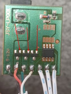
    Here are most likely the gates of the MOSFETs:
    Convert 9W RGBCW Chinese Smart Bulb (WB2L Module) to 12V 1A RGB WiFi Strip Controller
    Btw what is their marking?
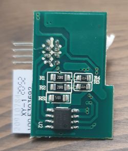
    You would need to detach old controller in SO8 case, desolder it, and attach WB2L...
    WB2L could be desoldered from it's board. It just needs a 3.3V and PWM Connection. Nothing more, it will work outside bulb pcb.
    WB2L also requires a 3.3V power supply, 5V would kill it, so you might need to use an LDO regulator like AMS1117.
    The ground should be common for both parts of the circuit.
    Futhermore, you'll of course have to flash WB2L with OpenBeken:
    https://www.youtube.com/playlist?list=PLzbXEc2ebpH0CZDbczAXT94BuSGrd_GoM

    I am not sure about using BP1638CJ . You could try, but this chip may be used for different purposes. Here is how it's connected in the bulb:
    Convert 9W RGBCW Chinese Smart Bulb (WB2L Module) to 12V 1A RGB WiFi Strip Controller
    Helpful post? Buy me a coffee.
  • ADVERTISEMENT
  • #3 20553453
    serter34
    Level 2  
    If I desolder the controller and solder WB2L, how could it control it? What do you think about the bulb circuit? Maybe it is easier to convert it than adding WB2L to the IR controller? If we manage to identify the pins, could we manage it? The big circuit is the power supply. The CW controller is on the LED PCB, the second PCB has the RGB controller and WB2L, so if we give the right V and amp, it could work like an ESP dev board?
  • #4 20553525
    p.kaczmarek2
    Moderator Smart Home
    This is only a suggestion, but here is a one way you could do that:
    1. remove WB2L from bulb board
    2. use our guides to flash OpenBeken to it
    3. ensure that OpenBeken access point shows up
    4. remove the SOIC chip from the IR LEDs board
    5. connect three PWMs of WB2L through resistors to the 3 transistors on the LED board (what are those transistors, btw?). Make sure to power WB2L from 3.3V, you need a stable 3.3V supply, when using LDO, keep in mind that you have 12V there, it may not be efficient, Tuya is using a step down 12V to 3.3V converter in their LED strips
    6. in obk, configure those PWM gpios as PWM, assign channels 1, 2, 3
    7. then you should be able to control LED via PWM

    OpenBeken firmware will allow you to easily manage pins in any way you want. You can even pair with HA, control from Tasmota Control app, write scripts, use NTP to fire event at given time of day, etc.

    Quote:

    What u think about bulb circiut maybe it is more easy to convert it to than adding to wb2l to ir controller?

    I don't know what kind of voltage is passed through those bulb LEDs. I would be afraid that I may burn my leds. I think the easiest way is the IR board mod. On a second glance, that bulb controller looks like a constant current one, but again, do you know how to adjust current setting resistors? Do you know what current you want to through your LED strip? etc, etc.
    Helpful post? Buy me a coffee.
ADVERTISEMENT