Here is a LN882HK based smart bulb (RGBCW) that a friend of mine got a bunch of on AliExpress and gave some surplus ones to me:
Link.
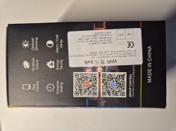
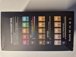
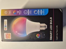
I can't seem to be able to identify a brand (if there is one), but it is advertised as being compatible with the Tuya ecosystem.
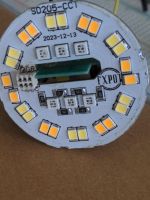
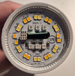
The bulb itself also looks very generic. Removing the lid shows an LED shield with an outer circle of alternating pairs of cold/warm white LEDs, and within 2 rows of 3 multi-cathode RGB LEDs
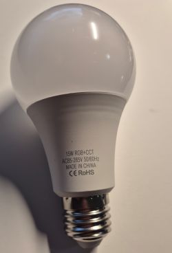
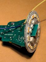
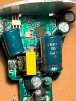
Removing some thermal glue from the other edge allows the LED shield to be removed, exposing the main PCB:
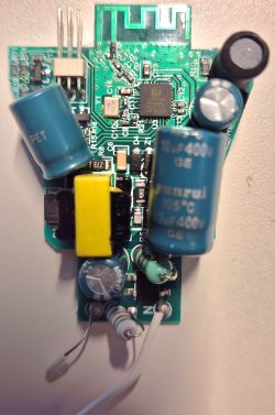
Note that the N contact is soldered to the tip of the bulb, whereas the P contact is just clamped between the upper end of the bulbs thread and the lower end of the plastic housing - no idea if this is considered a safety hazard, and also almost impossible to reassemble in the same way. I ended up pulling out the P wire and unsoldering the N wire from the PCB, trying carefully not to burn or break anything.
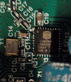
The controller used is a LN882HK, where neither the company in general nor the chip itself are known to me or anyone else I know.
Naturally it is also not supported by ESPHome, which led me to do an online search that quickly brought me here.
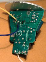
The backside exposed 2 pairs of UART TX/RX, where U0 is used for flashing and U1 probably as log terminal (I can only guess, since I didn't need to use it) , 3V3 supply and GND as well as a CEN (chip enable, not needed for flashing) and P21, which needs to be pulled to GND for flashing through UART.
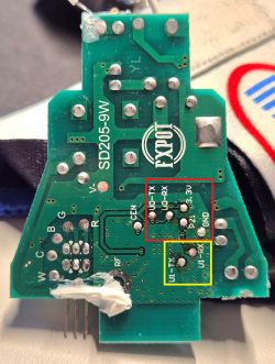
Red box: used for flashing
Yellow box: debug output (?)
Note that at the bottom right, you can see the cathode connectors of the corresponding LEDs (RGBCW) - the transistors driving them are connected to:
P09/GPIOA1 -> C
P12/GPIOA4 -> W
P13/GPIOA5 -> R
P14/GPIOA6 -> G
P15/GPIOA7 -> B
For flashing, I used a USB to UART/TTL adapter (3.3V) with the following connection:
U0-TX -> RX
U0-RX ->TX
GND -> GND
3V3 -> 3V3 (benchtop PSU, current limit 500mA)
P21 -> GND(during flashing)
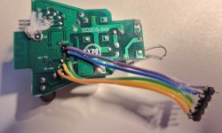
For flashing OpenBeken, I followed the description in the flashing guide in this forum(Link) as liked on github.
Flashing worked without any problems - after removing the short between GND and P21 and power cycling, I was able to connect to an OpenLN882H_C25E1088 hotspot.
Configuration and HomeAssistant integration worked without any hickups, so I'll not go into details here.
Using the GPIO finder, I managed to confirm the connections of the LED groups as I suspected from the PCB:
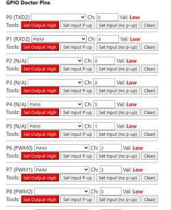
However, here is where I ran into some issues:
If I configure the pins as relays, I'm able to switch all 3 colors (RGB) plus cold/warm white without issue. If I configure them as PWM, I can only use G/B + warm white.
I'm not sure whether this is due to the LN882HK (maybe they use timer sharing for PWMs, or the pins need to be configured in a certain way) or just some oversight on my side - maybe I'll look into it some more if I find the time. Also if anyone has an idea what could be the issue, please reach out!
Summary:
My main aim was to have a dimmable warm white smart bulb, and thanks to OpenBeken and the instructions on this forum, I managed to get it working within on evening. The one issue remaining is the 5 simultaneous PWMs not working atm, but with an obscure chinese platform such as the LN882, and with such limited background information for developers available (that is not chinese), I think the mere fact that it is working at all is remarkable.
You have certainly done an amazing job portin OpenBeken to so many platforms as well as provide such detailed instructions on how to flash and use it!
Many thanks for that, I'll try to provide info on any compatible devices that I come across, as well as any bugs or issues with the software, should any pop up.
Link.


I can't seem to be able to identify a brand (if there is one), but it is advertised as being compatible with the Tuya ecosystem.
The bulb itself also looks very generic. Removing the lid shows an LED shield with an outer circle of alternating pairs of cold/warm white LEDs, and within 2 rows of 3 multi-cathode RGB LEDs


Removing some thermal glue from the other edge allows the LED shield to be removed, exposing the main PCB:

Note that the N contact is soldered to the tip of the bulb, whereas the P contact is just clamped between the upper end of the bulbs thread and the lower end of the plastic housing - no idea if this is considered a safety hazard, and also almost impossible to reassemble in the same way. I ended up pulling out the P wire and unsoldering the N wire from the PCB, trying carefully not to burn or break anything.
The controller used is a LN882HK, where neither the company in general nor the chip itself are known to me or anyone else I know.

Naturally it is also not supported by ESPHome, which led me to do an online search that quickly brought me here.
The backside exposed 2 pairs of UART TX/RX, where U0 is used for flashing and U1 probably as log terminal (I can only guess, since I didn't need to use it) , 3V3 supply and GND as well as a CEN (chip enable, not needed for flashing) and P21, which needs to be pulled to GND for flashing through UART.

Red box: used for flashing
Yellow box: debug output (?)
Note that at the bottom right, you can see the cathode connectors of the corresponding LEDs (RGBCW) - the transistors driving them are connected to:
P09/GPIOA1 -> C
P12/GPIOA4 -> W
P13/GPIOA5 -> R
P14/GPIOA6 -> G
P15/GPIOA7 -> B
For flashing, I used a USB to UART/TTL adapter (3.3V) with the following connection:
U0-TX -> RX
U0-RX ->TX
GND -> GND
3V3 -> 3V3 (benchtop PSU, current limit 500mA)
P21 -> GND(during flashing)

For flashing OpenBeken, I followed the description in the flashing guide in this forum(Link) as liked on github.
Flashing worked without any problems - after removing the short between GND and P21 and power cycling, I was able to connect to an OpenLN882H_C25E1088 hotspot.
Configuration and HomeAssistant integration worked without any hickups, so I'll not go into details here.
Using the GPIO finder, I managed to confirm the connections of the LED groups as I suspected from the PCB:

Code: JSON
However, here is where I ran into some issues:
If I configure the pins as relays, I'm able to switch all 3 colors (RGB) plus cold/warm white without issue. If I configure them as PWM, I can only use G/B + warm white.
I'm not sure whether this is due to the LN882HK (maybe they use timer sharing for PWMs, or the pins need to be configured in a certain way) or just some oversight on my side - maybe I'll look into it some more if I find the time. Also if anyone has an idea what could be the issue, please reach out!
Summary:
My main aim was to have a dimmable warm white smart bulb, and thanks to OpenBeken and the instructions on this forum, I managed to get it working within on evening. The one issue remaining is the 5 simultaneous PWMs not working atm, but with an obscure chinese platform such as the LN882, and with such limited background information for developers available (that is not chinese), I think the mere fact that it is working at all is remarkable.
You have certainly done an amazing job portin OpenBeken to so many platforms as well as provide such detailed instructions on how to flash and use it!
Many thanks for that, I'll try to provide info on any compatible devices that I come across, as well as any bugs or issues with the software, should any pop up.


