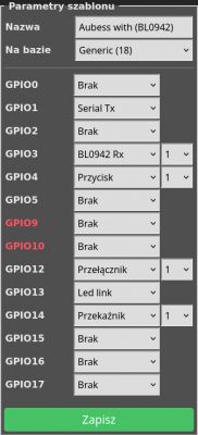
Aubess 16 Power monitor I replaced the Tuye CB2S with a TYWE2S (ESP) (I remembered correctly) I uploaded Tasmote there and everything works , including current and power measurement, but to my happiness I lack only a working button.
According to my conclusions Tuya had ( tacktswitch on the board ) a button under AD , the module TYWE2S also has AD on the same pin, but I do not know how to force Tasmote to recognize it and assign it to relay 1, maybe someone has figured it out or my conclusions are wrong and it is necessary / possible to do otherwise ?
I corrected
Add
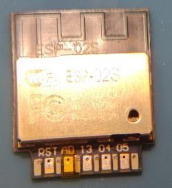
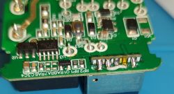
I have such a wonder I on the photo , I replaced the modules, I searched now and the next conclusions :
The ADC pin is shorted to ground with tactswitch
CB2S ADC pin
TYWE2S pin ADC
I can't find the information for mapping the TYWE2S ADC pin to the ESP pin , I don't know which GPIO on the Tasmot is the ADC pin on the TYWE2S
According to my conclusions Tuya had ( tacktswitch on the board ) a button under AD , the module TYWE2S also has AD on the same pin, but I do not know how to force Tasmote to recognize it and assign it to relay 1, maybe someone has figured it out or my conclusions are wrong and it is necessary / possible to do otherwise ?
I corrected
Add
I have such a wonder I on the photo , I replaced the modules, I searched now and the next conclusions :
The ADC pin is shorted to ground with tactswitch
CB2S ADC pin
Quote:8 ADC I/O ADC, which corresponds to P23 of the IC
TYWE2S pin ADC
Quote:8 ADC AI Same with module Silkscreen AD, ADC interface, a 10-bit-precision SAR ADC
Pin AD can only be used as an ADC interface but cannot be used as a common IO interface. Once not used, it needs to be pulled up. As an ADC input interface, the input voltage range is 0 to 1.0 V.
I can't find the information for mapping the TYWE2S ADC pin to the ESP pin , I don't know which GPIO on the Tasmot is the ADC pin on the TYWE2S


