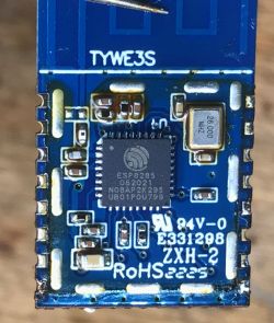
Recently, while uploading Tasmota to another series of WiFi-controlled light switches, I came across something that really surprised me. It was a TYWE3S module with non-standard pinouts that did not match the Tuya documentation. Here I will provide its RX, TX and GPIO0 location and information on how to change its input in such a case.
I found the module in the Appio 9605 light switch, but from what I saw, it is repeated in the entire Appio series. It may also be found in other products.
Seemingly, it's an ordinary TYWE3S:
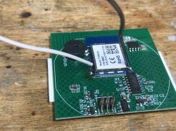
But standard flashing is not successful at all. For this reason, I desoldered it with hot-air:
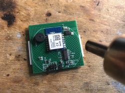
I also removed the screen and started analyzing:
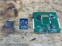
There is no ESP8266 + SPI Flash set inside, only ESP8285 with built-in 2MB memory.
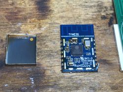
This TYWE3S has no GPIO information on the description layer:
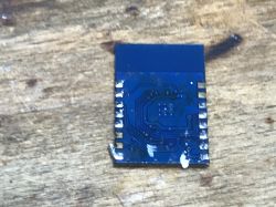
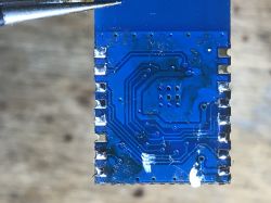
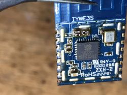
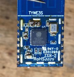
I was about to analyze the PCB carefully to see what goes where, but I found mentions of this module on the Internet:
https://github.com/arendst/Tasmota/discussions/16500
After soldering the wires according to the alternative pinout, I managed to upload Tasmota:
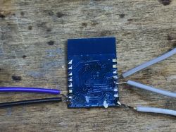
I flashed according to: https://www.elektroda.pl/rtvforum/topic3990951.html
Then I soldered the module into place.
The module can probably be flashed into the system just like the old TYWE3S (as long as the UART port is not occupied, e.g. by TuyaMCU), but at the moment I don't know how to determine from the outside whether the encountered TYWE3S is "new" or "old"...
Summary
This module is described as TYWE3S but has pinouts that are incompatible with it. I guess only the ground and power supply are in the same place, but I didn't check other GPIOs either, because it's faster to just set 4 relays on the Tasmota and test the GPIO options one by one than to write it down. It can be distinguished from the old TYWE3S only by the fact that there is one ESP8285 under the screen, not ESP8286 + memory chip.
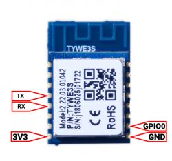
For reference, I will remind you of the pinouts of the old TYWE3S:
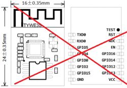
I really don't know how this could have happened and what was the motivation for such a pin swap, especially since all "newer" modules such as WB3S or CB3S have pinouts compatible with the old TYWE3S (even the UART location is the same), and here the UART is in a different place, but at least VDD/GND has not been changed, so there is probably no risk of damaging this module...
To sum up, I warn you - if you are unable to upload the firmware to TYWE3S, check if you have the version described in this topic.
Cool? Ranking DIY Helpful post? Buy me a coffee.


