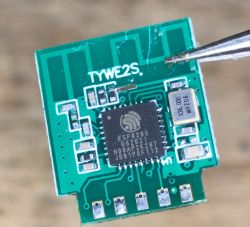
Here I will show you how to flash a new version of TYWE2S (ESP8285) Tuya WiFi module. Old TYWE2S had GPIO0 pad on the back, but this TYWE2S comes without any extra pads and has no markings. I've received one in a LSPA9-like smart socket with BL0937 power metering. Here I will attach the full pinout and mapping of this module. This module is still very easy to flash, you just need to know the GPIO mapping, which I will show below.
Let's start by looking at 'classic' TYWE2S, as per Tuya docs:
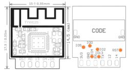
Pinout:
| Pin number | Symbol | I/O type | Function | 1 | 3V3 | P | Power supply pin (3.3 V) | 2 | IO5 | I/O | Same with module Silkscreen 05, GPIO_05, which corresponds to GPIO 5 (Pin 24 ) of IC | 3 | GND | P | Power supply reference ground | 4 | IO4 | I/O | Same with module Silkscreen 04, GPIO_04, which corresponds to GPIO 4 (Pin 16) of IC | 5 | RX | I/O | UART0_RXD (used to display the internal information of the module) | 6 | IO13 | I/O | Same with module Silkscreen 13, GPIO_13, which corresponds to MTCK (Pin 12) of IC | 7 | TX | I/O | UART0_TXD (used to display the internal information of the module) | 8 | ADC | AI | Same with module Silkscreen AD, ADC interface, a 10-bit-precision SAR ADC | 9 | IO12 | I/O | Same with module Silkscreen 12, GPIO_12, which corresponds to MTDI (Pin 10 ) of IC | 10 | RST | I/O | Hardware reset pin (active low, a resistor has been pulled up internally) | 11 | IO14 | I/O | Same with module Silkscreen 14, GPIO_14, which corresponds to MTMS (Pin 9 ) of IC |
Extra pads:
| Pin number | Symbol | I/O type | Function | 12 | IO4 | I/O | GPIO_04, which corresponds to GPIO 4 (Pin 16) of IC | 13 | IO13 | I/O | GPIO_13, which corresponds to MTCK (Pin 12) of IC | 14 | IO2 | I/O | UART1_TXD, (an interface for displaying information about the module) | 15 | RST | I/O | Reset pin | 16 | IO5 | I/O | GPIO_05, which corresponds to GPIO 5 (Pin 24) of IC | 17 | IO0 | I/O | GPIO_0 (in the module power-on initialization process, use with caution) |
My flashing procedure here is very simple - solder 3.3V, GND, RX, TX and GPIO0, attach GPIO0 to ground and then connect power. Module will boot into bootloader mode, so esptool.py can be used to flash it:
esptool.py write_flash 0 tasmota.bin
Then you will have to disconnect it from power, disconnect IO0 from GND, and power it again, so Tasmota can run.
But recently I have received a strange variation of TYWE2S:
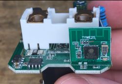
It was in a no-name power metering socket in a LSPA9 shape.
After desoldering, I realized that it has no markings:

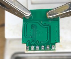
So I have opened ESP8285 datasheet and wrote down the pinout, in hope to find GPIO0 easily accessible:
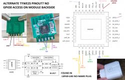
The GPIO0 is in place of AD pin of old TYWE2S. This is new to me. It's good that it's still routed out.
Remaining pads seem to match old TYWE2S. I don't know why Tuya made that change.
Conclusion
I haven't been aware about this TYWE2S variation up until now. At first I was worried that I will have to solder directly to QFN pad, but luckily the GPIO0 was routed out in the place of ADC pad. I don't know why Tuya changes TYWE2S form and is it indeed a new version of the module, but at least I know how to flash it with Tasmota easily.
Have you also encountered a TYWE2S variation like that? Let me know in the comments!
Cool? Ranking DIY Helpful post? Buy me a coffee.


