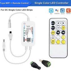
This is a $7 LED controller that I got from aliexpress.
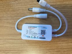
Opening it up revealed that it uses a CB3S/BK7231N module.
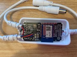
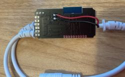
As I was not in the mood to try desoldering the module, or to solder additional attachments to the board, I checked if the TX/RX pins are available on the debug pins to the side. This sadly was not the case - only VCC and GND were broken out there. However, it turns out that I have a pogo mini clamp laying around that kind of fit on the rx/tx pins of the CB3S - and I used some probe clips to attach to GND/VCC.
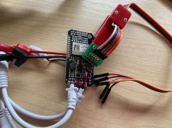
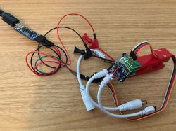
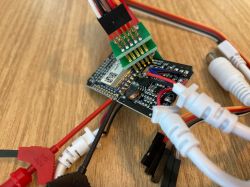
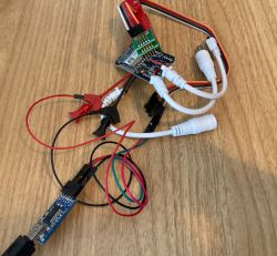
Even though this looks a bit adventurous - this approach worked fine, and flashing worked without any problems.
If you want to replicate this - the black probe clip (rightmost debug connector) is GND, the red one next to it is VCC (3.3V). Only the two left probe clips are used; they attach to pin 15 (RXD) and 16 (TXD) of the CB3S; 16 is the pin closest to the antenna.
After flashing, PIN 26 is the PWM pin for the LED strip. I did not yet try the remote (I don't really need it for my current use-case).


Opening it up revealed that it uses a CB3S/BK7231N module.


As I was not in the mood to try desoldering the module, or to solder additional attachments to the board, I checked if the TX/RX pins are available on the debug pins to the side. This sadly was not the case - only VCC and GND were broken out there. However, it turns out that I have a pogo mini clamp laying around that kind of fit on the rx/tx pins of the CB3S - and I used some probe clips to attach to GND/VCC.


Even though this looks a bit adventurous - this approach worked fine, and flashing worked without any problems.
If you want to replicate this - the black probe clip (rightmost debug connector) is GND, the red one next to it is VCC (3.3V). Only the two left probe clips are used; they attach to pin 15 (RXD) and 16 (TXD) of the CB3S; 16 is the pin closest to the antenna.
After flashing, PIN 26 is the PWM pin for the LED strip. I did not yet try the remote (I don't really need it for my current use-case).


