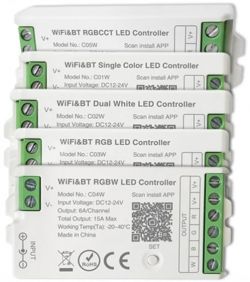
Here I will present the short teardown and OpenBK7231 programming procedure for a family of LED controllers.
They are based on CBU module, BK7231N
Unfortunately the CBU module is sandwiched between two boards, making access difficult.
Here is the generic controller board, both sides:
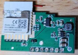
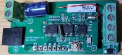
The generic controller has PWM outputs RGBCW to the mode-specific base board.
The PWM outputs are not attached to the CBU module!
The CBU module is connected via UART to a CMS32L051 microcontroller, which is also attached to the bluetooth radio and provides the PWM outputs buffered by a 74HC245.
I did not know how to get OpenBeken to connect to this CMS32L051 over uart, so the plan was to remove it and jumper to the CBU PWM pins:
To flash the CBU I desoldered the CMS32L051 which gave access to RX/TX on pins 5/6 (there is a series 1k resistor on both lines)
Connect:
CBU:16 RX or CMS32L051:6 - FTDI TTL-232R-3V3 Orange
CBU:15 TX or CMS32L051:5 - FTDI TTL-232R-3V3 Yellow
Flashing with the windows tool and a 3v3 FTDI cable was smooth.
Note: I had disconnected 1k resistors and connected directly on CBU pins.
I know with CMS32L051 installed, flashing is not possible.
I assume flashing will work through 1k resistors if CMS32L051 is removed, but this was not tested.
The RCBCW PWM lines are available on CMS32L051 pins 13/14/15/16/10
I have a C02W so I jumpered:
CMS32L051:10 to CBU:8 or P8, and configured this as Channel 5
CMS32L051:16 to CBU:9 or P7, and configured this as Channel 4
Doing this without desoldering the controller from the base board would be quite challenging but not impossible. I did split the boards apart as part of my investigation, but it was difficult to remove enough solder even with a desoldering gun.
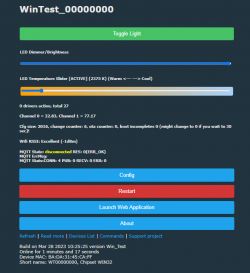
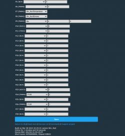
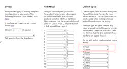
For some reason OpenBeken would not set the outputs (i.e. Channel 0 = 0.00, Channel 1 = 0.00, Channel 2 = 0.00, Channel 4 = 0.00, Channel 5 = 0.00) if I only configured channels 4 and 5.
So I also configured P6 as channel 1 and P9 as channel 2 which makes this a RGBCW device, and now channels 4/5 work, with channels 1/2 not connected to anything and channel 3 not configured.
I now have a C02W working with OpenBeken.
There is very likely a better technique, but this was my first OpenBeken device. Any advice would be welcome - I want several such modules but I'm not sure it's worth the hassle.
They are based on CBU module, BK7231N

Unfortunately the CBU module is sandwiched between two boards, making access difficult.
Here is the generic controller board, both sides:


The generic controller has PWM outputs RGBCW to the mode-specific base board.
The PWM outputs are not attached to the CBU module!
The CBU module is connected via UART to a CMS32L051 microcontroller, which is also attached to the bluetooth radio and provides the PWM outputs buffered by a 74HC245.
I did not know how to get OpenBeken to connect to this CMS32L051 over uart, so the plan was to remove it and jumper to the CBU PWM pins:
To flash the CBU I desoldered the CMS32L051 which gave access to RX/TX on pins 5/6 (there is a series 1k resistor on both lines)
Connect:
CBU:16 RX or CMS32L051:6 - FTDI TTL-232R-3V3 Orange
CBU:15 TX or CMS32L051:5 - FTDI TTL-232R-3V3 Yellow
Flashing with the windows tool and a 3v3 FTDI cable was smooth.
Note: I had disconnected 1k resistors and connected directly on CBU pins.
I know with CMS32L051 installed, flashing is not possible.
I assume flashing will work through 1k resistors if CMS32L051 is removed, but this was not tested.
The RCBCW PWM lines are available on CMS32L051 pins 13/14/15/16/10
I have a C02W so I jumpered:
CMS32L051:10 to CBU:8 or P8, and configured this as Channel 5
CMS32L051:16 to CBU:9 or P7, and configured this as Channel 4
Doing this without desoldering the controller from the base board would be quite challenging but not impossible. I did split the boards apart as part of my investigation, but it was difficult to remove enough solder even with a desoldering gun.
For some reason OpenBeken would not set the outputs (i.e. Channel 0 = 0.00, Channel 1 = 0.00, Channel 2 = 0.00, Channel 4 = 0.00, Channel 5 = 0.00) if I only configured channels 4 and 5.
So I also configured P6 as channel 1 and P9 as channel 2 which makes this a RGBCW device, and now channels 4/5 work, with channels 1/2 not connected to anything and channel 3 not configured.
I now have a C02W working with OpenBeken.
There is very likely a better technique, but this was my first OpenBeken device. Any advice would be welcome - I want several such modules but I'm not sure it's worth the hassle.
Cool? Ranking DIY


