logo elektroda
logo elektroda
X
logo elektroda

Flashing Tasmot software on MS-103 with Tuya WB3S chip: errors and possible paths

kirol1 2352 13
ADVERTISEMENT
Treść została przetłumaczona polish » english Zobacz oryginalną wersję tematu
  • #1 20697155
    kirol1
    Level 3  
    Hi,
    I own a "Temperature and humidity Smart Switch module". Model MS-103, and I have made several attempts to flash the software to the tasmota. The device has a motherboard with model NH-2TH16-V1.1 and a Tuya WB3S chip. Detailed appearance and description of the device in this thread on elektroda.com
    https://www.elektroda.pl/rtvforum/topic3966365.html

    First attempt of flashing was using the project ct-Open-Source/tuya-convert
    https://github.com/ct-Open-Source/tuya-convert
    Unfortunately during the moment when the device is supposed to be flashing it pops up that the device has too new software.

    The second attempt was made using openshwprojects/OpenBK7231T_App
    https://github.com/openshwprojects/OpenBK7231T_App
    I connected the UART to USB converter connecting to 4 pins TXD1 , RXD1 GND and VCC directly to WB3S module.
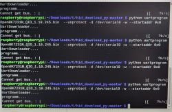
    Unfortunately during uploading/executing the backaup the message "Getting bus failed, will try again" pops up.
    Is it required to break any path for the module to be able to be flashed?
    How is the easiest way to upload the tasmote?

    Additional device view:
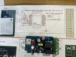
    Switch module with circuit board image and connection diagram. .
  • ADVERTISEMENT
  • #2 20697266
    p.kaczmarek2
    Moderator Smart Home
    Hello, in this case the device is built on WB3S - BK7231T, not ESP, so Tasmota will not upload.

    You can upload OpenBeken, which will give you basic compatibility with Tasmota protocols (some commands, JSON format, Tasmota Device Groups support) and equivalents of some of Tasmota's functionality (Home Assistant, scripts, etc).

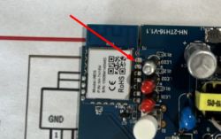
    Flashing may not work due to something being connected to RX or TX, so as you wrote, you may need to cut the path. I would first recommend that you check exactly where this TX1 or RX1 (also TXD1/RXD1 in the screengrab, it's the same thing) is connected - do you have a multimeter?

    Looking at the photo:
    Close-up of a PCB with a highlighted WB3S module.
    I have the impression that RXD1 is connected somewhere.

    But another question - when the flasher is waiting for "getting bus" do you do a power off/power on cycle? Do you disconnect and connect the power? This is the basics, if you don't do this it definitely won't work. The flasher must "catch" the BK7231 boot moment and only then can it upload the firmware.

    Here you have a video of WB3S programming:


    Additionally note - as of recently we have a new flasher:
    https://github.com/openshwprojects/BK7231GUIFlashTool
    I also highly recommend making a copy of the original batch before uploading the new software. Read option in linked flasher .

    Added after 2 [minutes]:

    Additionally - how do you power this WB3S? I'd rather not recommend powering it from a USB to UART converter, although it depends what kind you have. The 3.3V LDO stabiliser there may not have enough current capacity. You need a robust 3.3V source.
    Helpful post? Buy me a coffee.
  • ADVERTISEMENT
  • #3 20697310
    kirol1
    Level 3  
    During getting bus I short-circuit the Cen pin to GND.
    As a converter I use NodeMCU with a jumper between G with RST to skip the ESP8266 module.
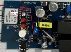
    I have measured and Txd1 is connected to the blue capacitor (pin from the bottom). The Rxd1 pin is connected to the diode next to it (pin on the left).
    Is it theoretically sufficient that I disconnect the leg from the capacitor and the flashing should be successful? (Unplugging the leg marked in yellow)

    Connections between the TXD1 and RXD1 ports on the WB3S and NH-2TH16-V1.1 board

    PCB with WB3S module, capacitors, and connectors, with TXD1 and RXD1 pins highlighted. .
  • #4 20697324
    p.kaczmarek2
    Moderator Smart Home
    I don't think TXD1 can be connected to the Y capacitor connecting the "hot" ground to the "cold" ground. There is no pad at TXD1. Maybe you inadvertently hooked the probe to the WB3S screen? The WB3S screen is at potential ground, so probing it to the leg of this capacitor should show 0 ohms.

    The CEN method is tricky, shorting the CEN to ground must take 0.25 seconds, I sometimes rub two contact wires together so it can catch. It is better to do a power off and power on cycle.

    Maybe disconnecting the diode from RXD1 will help, but also note what I wrote about CEN.
    Helpful post? Buy me a coffee.
  • #5 20697396
    kirol1
    Level 3  
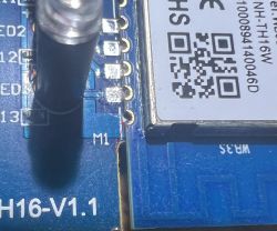
    From frequently applying the tester and leads, I made a slight abrasion on the laminate right next to the TXD1 contact and therefore the full connection I marked was coming out. After more careful application of the tester to the upper component no connections come out.


    I have shorted the laminate next to the TXD1 pin:
    Close-up of a circuit board with marked abrasion next to pin TXD1.

    During the first flashing I definitely had the TXD1 pin shorted to the laminate. I have just now attempted to flash by clearing this error and applying your advice about cutting power to the 3.3 volt pin instead of shorting CEN to GND. Unfortunately the flashing attempts remain at the same stage. Would it be easier to remove the diode or would I desolder the whole module with a heat gun ( I don't have hot air and I can set the heat gun to 300 or 500 degrees)?
  • #6 20697419
    p.kaczmarek2
    Moderator Smart Home
    This is a bit bad, because now when you try to solder the pins to TXD1 the solder can also catch the board at the bottom and short out TXD1 to ground. You need to solder carefully. Although...
    How did you try to program as I don't see any solder marks on TXD1 and RXD1? Applying the wires is not a very reliable method, especially as the whole programming process takes a bit.

    Well, but okay, it doesn't change much. In summary:
    - solder (?) temporarily this LED from RXD1
    - when touching the wire to TXD1 (or soldering), touch only to TXD1, not to ground
    - start the flasher, switch off the power supply and connect it again
    In case of problems swap RX and TX with places.

    When switching off the power you are supposed to switch off only the power to the board itself with WB3S, you are not supposed to pull out the USB to UART converter completely from the USB, because then the COM port will disappear and the serial connection will break completely.
    Helpful post? Buy me a coffee.
  • ADVERTISEMENT
  • #7 20702235
    kirol1
    Level 3  
    I have successfully uploaded OpenBeken! Out of frustration that I couldn't program WB3S correctly I soldered it out completely. After soldering directly under the 4 pins I still failed to program it. The problem lay with those cheap cables that come with the kits on the Arduino. I had already cut male cables which I soldered under the board, but to connect them I used a cable with two female connectors (as an adapter). Unfortunately, the quality of the connection was so poor that I was never able to program it and was stuck at the "Getting bus failed, will try again" stage. After soldering a cable with a female connector, the problem disappeared and I was able to download the soft from the board and upload the new OpenBeken the first time. Now all that is left is to set the pins properly in the configuration. I will try to do based on this material you sent above with the light switch. I'm wondering how I should configure the one-wire protocol for the temperature sensor.

    Added after 18 [minutes]:

    Would it in theory be possible to connect additional temperature sensors to this device?
  • ADVERTISEMENT
  • #8 20702379
    p.kaczmarek2
    Moderator Smart Home
    It depends on the sensor. You can connect many sensors from the DHT family. DHT11, DHT12, etc, are all supported. SHT30 can only be connected one, as can CHT8305, MCP9808. The DS18B20 on the other hand is in the process of being implemented and will not work at the moment.

    What is this device specifically and what sensor do you want to attach?

    EDIT: I looked at the linked topic from the com, there it mentions the DS18B20. If you want a driver for this sensor, let me know, it is not ready yet, I would have to port some library.
    Helpful post? Buy me a coffee.
  • #9 20705595
    kirol1
    Level 3  
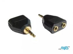
    I am very keen and would be very keen to be able to connect two thermometers. Let me know if I can help you somehow to port or test it. If you would like we can arrange a specific time and compile live on this board. According to what I understand the DS18B20 can be connected in parallel to each other and in that case if this device has a female jack input and attached one piece of thermometer with a male jack input then it could be connected through such a binary.

    Mini jack splitter :
    Mini jack splitter with two female ports and one male connector. .
  • #10 20705607
    p.kaczmarek2
    Moderator Smart Home
    I'll let you know if there's any progress with the DS18B20, and maybe you could use the DHT11 for now? It's all ready to go under it:


    And you can connect several....
    Helpful post? Buy me a coffee.
  • #11 20707695
    kirol1
    Level 3  
    Unfortunately the DHT11 is not sold as a metal sampler. I need to attach it to the metal risers of the hot water circuit. Can you somehow direct me which library I should use to make it work? Alby is it possible to bypass the one wire protocol with a single DS18B20 thermometer connected?
  • #12 20713500
    kirol1
    Level 3  
    I have configured the pins according to this post https://www.elektroda.com/rtvforum/topic3966365.html
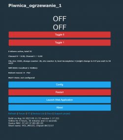
    Everything works very well excluding the one-wire protocol. I am impressed with the interface it is repaired clear and very comfortable to use. Responsiveness is excellent. I tried to poke around to get any digital reading from the DS18D20 but without any positive results.

    Configured device without temperature reading.
    WiFi device control panel with Toggle buttons and OFF status.

    PS at https://openbekeniot.github.io/webapp/devicesList.html
    The correct configuration is available (you have to remove pin 7 (temperature reading) from it):
    Code: JSON
    Log in, to see the code
    .
  • #13 20714350
    p.kaczmarek2
    Moderator Smart Home
    DS18D20 you would have to port the corresponding driver to our driver format in style:
    https://github.com/openshwprojects/OpenBK7231T_App/blob/main/src/driver/drv_mcp9808.c
    You must have OneWire for this, which we also do not have yet in OBK.

    I have this in mind, I plan this driver for you to embrace, but every day there are other feature requests and also hard with time, yesterday I did:
    https://github.com/openshwprojects/OpenBK7231T_App/blob/main/src/driver/drv_adcSmoother.c

    @kirol1 to what extent do you know programming, C language and so on? If so, I could guide you a bit and you would help with this driver, but unfortunately you need to know C to get something going with it.
    Helpful post? Buy me a coffee.

Topic summary

The discussion revolves around flashing Tasmota software onto the MS-103 temperature and humidity smart switch module, which utilizes a Tuya WB3S chip. Initial attempts to flash the device using the ct-Open-Source/tuya-convert project failed due to the device having newer software. Subsequent attempts with OpenBK7231T_App encountered issues related to UART connections, specifically "Getting bus failed" errors. Users suggested checking connections, cutting paths, and ensuring proper power cycling during the flashing process. Eventually, one user successfully uploaded OpenBeken after addressing connection quality issues with the wiring. The conversation also touched on configuring the device for temperature sensors, particularly the DS18B20, and the need for a corresponding driver, which is in development.
Summary generated by the language model.
ADVERTISEMENT