logo elektroda
logo elektroda
X
logo elektroda

[BK7231N] [CBU] AVATTO Tuya Brazil 4x4 WiFi Wall Switch 4/6 Gang

tomanyusers 2418 29
ADVERTISEMENT
  • #1 20563465
    tomanyusers
    Level 3  
    This is a short teardown of the AVATTO Tuya Brazil 4x4 WiFi Wall Switch, 4/6 Gang Light Switch.

    This is available on AliExpress

    This is very similar to https://www.elektroda.com/rtvforum/topic3963972.html#20484235 but also has a backlight. I assume that this is just another channel.

    Disassembly is very easy, the glass front cover unclips and the two PCBs can be pulled apart.
    The front PCB has the touch sensors and CBU module and the rear PCB has all the power electronics.


    [BK7231N] [CBU] AVATTO Tuya Brazil 4x4 WiFi Wall Switch 4/6 Gang [BK7231N] [CBU] AVATTO Tuya Brazil 4x4 WiFi Wall Switch 4/6 Gang [BK7231N] [CBU] AVATTO Tuya Brazil 4x4 WiFi Wall Switch 4/6 Gang [BK7231N] [CBU] AVATTO Tuya Brazil 4x4 WiFi Wall Switch 4/6 Gang [BK7231N] [CBU] AVATTO Tuya Brazil 4x4 WiFi Wall Switch 4/6 Gang


    The App looks like this and you can see the Backlight control.
    [BK7231N] [CBU] AVATTO Tuya Brazil 4x4 WiFi Wall Switch 4/6 Gang [BK7231N] [CBU] AVATTO Tuya Brazil 4x4 WiFi Wall Switch 4/6 Gang


    I have tried to sniff the comms between the [CBU] and the [HK32F030MF4P6] with no success. I am not sure what I am doing wrong. Maybe someone can point me in the correct direction. I am reluctant to flash the device until I know that I will be able to use it with OpenBK.
  • ADVERTISEMENT
  • #2 20563480
    p.kaczmarek2
    Moderator Smart Home
    Hello, it almost certain that OBK will run on that well.

    You can try doing packet capture on RX/TX lines with 9600 or 115200 baud to be sure.

    Here's TuyaMCU analyzer:
    https://www.elektroda.com/rtvforum/topic3970199.html#20528459

    Still, OBK flash tool can make a 2MB backup and restore it easily, so maybe just go ahead and flash it and we will figure out the remaining things together.
    https://github.com/openshwprojects/BK7231GUIFlashTool
    Helpful post? Buy me a coffee.
  • #3 20563515
    tomanyusers
    Level 3  
    Hi.
    My issue is that I'm not seeing any data on TX or RX at all, at any baud.

    My USB to Serial seems to be working. If I bridge the TX and RX lines I am able to receive whatever I send. I used it yesterday to flash a Sonoff device with no issues.
    I'm going to pick up a different USB to Serial later this week maybe I will have better luck.
  • #4 20563549
    p.kaczmarek2
    Moderator Smart Home
    Hmm, you really should see some data. Are you saying that device is not a TuyaMCU? We can add a support for a new protocol, if that's needed. Is TX/RX connected to the MCU? Which pins?

    Those 0 resistors, aren't they as jumpers on RX/TX lines?

    How good are you soldering skills? Removing those resistors to flash OBK, soldering them in place, it's like a 5 minutes deal if you know how to do it.

    In worst case you can remove them again and flash back factory firmware.
    Helpful post? Buy me a coffee.
  • #5 20565974
    tomanyusers
    Level 3  
    Hi

    There are no comms between the [CBU] and the [HK32F030MF4P6] via serial. It is however connected. The resistors R11-R14 are selectable between the first and second serial on the [CBU]. At the moment set to use the first (default) serial. There are no serial coms on either serial.

    There are also lines from P14 and P16 that are linked to the [HK32F030MF4P6]. Think there are the SPI pins.
    I'm using the pin symbols from Tuya Dev Docs

    The Tx and Rx are connected to Pins 13 and 14 on the [HK32F030MF4P6]

    The relays are also wired directly to the [CBU] on these pins P24,P26,P6,P7,P8,P28.

    I think the Wifi LED might be on P17 (Not confirmed)

    The ADC pin is also linked to the [HK32F030MF4P6]. Not sure why.

    Some of the other lines from the [CBU] also seem to link to the other IC's.
    P16 to U4 (Pin7)
    P9 to U5 (Pin7)
    U4 and U5 are unmarked. There are two of them I suspect that there are IC's responsible for touch sensing. Also Unconfirmed.

    I'm not sure how to proceed from here.
  • ADVERTISEMENT
  • #6 20566058
    p.kaczmarek2
    Moderator Smart Home
    A USB logic analyzer could help. Those can be very cheap and easy to use. I've bought (thanks to the donation funds) for about 10$ not so long ago. That tool can show the protocol data, and we would immediatelly know whether it's UART, or I2C, or SPI, or anything. It would also show us the bytes that are sent, so we can tell how to implement it in our custom driver.
    Helpful post? Buy me a coffee.
  • #7 20759852
    arlindo
    Level 5  

    I have two devices like that (6 Gang) with a CBU module, but I have zero skills with soldering to remove or replace the CBU. Maybe it's possible to use the Tuya CloudCutter (https://github.com/tuya-cloudcutter/tuya-cloudcutter) to change the firmware. Currently, my two devices are used in Home Assistant with HACS's Local Tuya integration. I'll order a new one to conduct some tests, and in the worst case, replace the CBU module (https://templates.blakadder.com/ESP8685-WROOM-06.html). I'll ask a friend to handle the soldering process to avoid destroying it! :-D
  • #8 20939880
    guilhermemaciel
    Level 3  

    I'm bumping this one because I'm having some issues. Managed to flash the CBU, I can connect to the internal WiFi, but when I set the new WiFi, it won't connect. I'm not exactly sure how to further diagnose this issue.
  • #9 20940121
    p.kaczmarek2
    Moderator Smart Home
    Does the problem happen only on one particular device, or is it common among all of your BKs?
    Helpful post? Buy me a coffee.
  • ADVERTISEMENT
  • #10 20940162
    guilhermemaciel
    Level 3  

    I've found that this device refuses to connect to my main Wi-Fi, it connected just fine to my guest one. It's the only device with CBU that I have, everything else is CB3S and they connected just fine to the main Wi-Fi.

    I think the reason is the space in the name of the main Wi-Fi.

    Anyway, I'm using this to migrate all of my smart stuff into the guest network.
  • #11 20940163
    p.kaczmarek2
    Moderator Smart Home
    Where is that space? Is it in the middle of the name, or at the beginning, or at the end?
    Helpful post? Buy me a coffee.
  • #12 20940173
    guilhermemaciel
    Level 3  
    Midle, its like "Mount Sinai"
  • #13 20990803
    arlindo
    Level 5  

    Hi guilhermemaciel,

    Did you fix your WiFi problem?

    Would you mind sharing the details of what you did to flash the Avatto? Do the buttons work properly?

    Thanks!
  • #14 20990804
    guilhermemaciel
    Level 3  

    Yeah, I didn't know I hadn't posted the solution, it was a flag on the startup that was causing this.

    Everything works just fine. You just need to know that the button color is attached to the relay status by wire, you can't toggle it separately.
  • #15 20992617
    arlindo
    Level 5  
    That's wonderful news. I've had many troubles using Tuya Cloud (e.g., frequent disconnections) with Home Assistant. Perhaps using the local network would provide better stability than relying on Tuya Cloud.

    But how do you flash the firmware onto the hardware? Do you use software like CloudCutter or do you flash it via wire? If you use flash by wire, which pins are used?
  • #16 20992631
    p.kaczmarek2
    Moderator Smart Home
    I am always flashing devices by wires. The pins are depending on the device, but it's almost always:
    - GND
    - 3.3V
    - TX1
    - RX1
    So, power and UART 1.

    We have a full playlist of flashing guides for IoT devices on Elektroda YT channel:
    https://www.youtube.com/watch?v=L6d42IMGhHw&list=PLzbXEc2ebpH0CZDbczAXT94BuSGrd_GoM
    You can also search our devices list for "detailed" articles:
    https://openbekeniot.github.io/webapp/devicesList.html

    Btw which flag caused problems?
    Helpful post? Buy me a coffee.
  • #17 20992660
    arlindo
    Level 5  

    My hardware is exactly the same as the one mentioned here (i.e., AVATTO Tuya Brazil 4x4), which has a CBU module. I've heard about many problems regarding flashing or even sniffing this module, which makes me fear flashing it and potentially bricking it.
  • #18 21130024
    yasirshahzad918
    Level 5  
    Can anyone tell me which touch IC is used here? I am looking for a touch IC for my custom touch PCB.
  • #19 21132382
    arlindo
    Level 5  
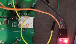
    Well, I gathered some courage and tried to read/flash my Avatto (CBU) to OpenBeken. I used the CEN and GND jumpers to try to put the CBU in flash mode. The soldering scheme is shown in the image below.

    Close-up of a circuit board with connected wires and a CBU chip.

    During this process, I confirmed what @tomanyusers said in the first message of this topic: it is not possible to read/write the CBU chip on the board. It might be possible if the chip is removed from the board, but I need to gather more courage to do that!

    Maybe @guilhermemaciel can give more details about his flashing process; this would help a lot!
  • #20 21132899
    p.kaczmarek2
    Moderator Smart Home
    Maybe you can just cut the traces? Where are the RX1/TX1 traces going on the board? I can't see clearly on the photo, the wires are occluding that
    Helpful post? Buy me a coffee.
  • #21 21132944
    arlindo
    Level 5  
    Hmm... it's not a photo problem; the traces are on the other side of the board, connecting TX1 and RX1 to R13 and R14. Those are really tiny traces, and I'm not comfortable cutting them. I tried to use a desoldering pump to break the connection between the CBU and the board on TX1/RX1, but without success. I think I need more equipment and much more skill with soldering. However, I really think that CBU is a piece of junk, so I bought an ESP8685-WROOM-06-H4 (ESP32-C3) to replace it. Of course, I'll be helped by a friend to do it! Before burning the CBU in a fire, I will try to flash it again, this time with it off the board.

    >>21132899
  • #22 21132948
    p.kaczmarek2
    Moderator Smart Home
    I would find a CBU very useful for research and testing, as it has P16 routed out, so it can drive WS2812B.
    Helpful post? Buy me a coffee.
  • #23 21133238
    arlindo
    Level 5  
    Sorry if I was rude. I think that CBU is useful in many situations, but it is not stable here. I changed my entire Wi-Fi network to Ubiquiti solutions, thinking that it would help stabilize Tuya IoT, but it did not! All ESP (Tasmota) devices have stayed connected for weeks or months, but Tuya devices restart their Wi-Fi connection every hour.

    Maybe the software inside CBU is the real problem, which is why I want to change to OpenBeken. Unfortunately, the board does not help me in this process. But, I'll take a breath and try two approaches: i) Tuya CloudCutter, and ii) remove/disconnect RX1/TX1 as you suggested. After all, I want to help in this thread! :-)
  • #24 21133285
    p.kaczmarek2
    Moderator Smart Home
    Don't worry, it didn't sound rude. We're here to help.
    Well, if you want to swap CBU for ESP, then you still have to do the desoldering, so it won't hurt to try flashing first. It should flash well outside the circuit. Then you can try if OBK is more stable. And if you still decide to get the rid of it, you can consider just sending me one for testing (depending on where you are from...)
    Helpful post? Buy me a coffee.
  • #25 21209658
    arlindo
    Level 5  
    Hi guys,

    I did some tests and I'm bringing back my findings to share with you:

    Firstly, it's not possible to swap the CBU chip for the ESP8685-WROOM-06-H4 with 100% compatibility, as I initially thought! These two chips have significant differences in their IO (and their positions), which makes it difficult to get them to work.

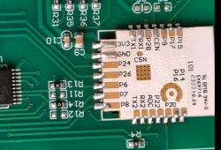
    Secondly, it was necessary to remove the CBU chip to reprogram it. In this case, there was no difficulty in flashing; OpenBeken works like a charm after flashing! As you can see in the figure, the R13 and R14 (which connect TX1 and RX1 to the HK32F030MF4P6) are zero-ohm resistors. What is the function of a zero-ohm resistor here? Is it just a jumper? If so, it can be removed for flashing and then reconnected with soldering afterward.

    Close-up of a PCB with an ESP8685-WROOM-06-H4 module and zero-ohm resistors R13 and R14.


    Finally, the CBU and OpenBeken work perfectly with the "AVATTO Tuya Brazil 4x4 WiFi Wall Switch 6 Gang," and the pin configuration is below (I'll share this on GitHub ASAP).
    
    "pins": {
      "6": "Rel;3",
      "7": "Rel;2",
      "8": "Rel;1",
      "9": "Btn;6",
      "10": "Btn;5",
      "11": "Btn;4",
      "14": "Btn;1",
      "16": "Btn;2",
      "17": "WifiLED;10",
      "20": "Rel_n;0",
      "23": "Btn;3",
      "24": "Rel;5",
      "26": "Rel;4",
      "28": "Rel;6"
    }


    Thanks for all the help!
  • #26 21209663
    p.kaczmarek2
    Moderator Smart Home
    The resistors on RX/TX traces are most likely just jumpers. It should work fine without them. As you said, it;s not possible to flash while the connection to TuyaMCU is present. That's why we either cut the traces (desolder resistors if possible) or desolder whole MCU/WiFi module.
    Helpful post? Buy me a coffee.
  • #27 21210029
    arlindo
    Level 5  
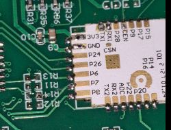
    I confirm that! I removed R13 and R14 in another device, flashed the firmware, and used soldering to reconnect the jumpers. Everything is working normally, but now with OpenBeken!

    Close-up of a printed circuit board with an attached module and visible soldering.


    Added after 1 [hour] 26 [minutes]:

    What do I need to do for this device to appear in the device list (https://openbekeniot.github.io/webapp/devicesList.html)?
  • #28 21210364
    p.kaczmarek2
    Moderator Smart Home
    You need to post a full JSON template copied from the web app, and also fill the image and "wiki" (forum) links there. Then I will add it. Also , of course, fill device name field, model, etc
    Helpful post? Buy me a coffee.
  • ADVERTISEMENT
  • #29 21212984
    arlindo
    Level 5  
    Ok! Here you are:

    
    {
      "vendor": "AVATTO",
      "name": "AVATTO Tuya Brazil 4x4 WiFi Wall Switch",
      "model": "6 Gang",
      "chip": "BK7231N",
      "flags": "1028",
      "keywords": [
        "avatto",
        "6gang",
        "cbu"
      ],
      "pins": {
        "6": "Rel;3",
        "7": "Rel;2",
        "8": "Rel;1",
        "9": "Btn;6",
        "10": "Btn;5",
        "11": "Btn;4",
        "14": "Btn;1",
        "16": "Btn;2",
        "17": "WifiLED;10",
        "20": "Rel_n;0",
        "23": "Btn;3",
        "24": "Rel;5",
        "26": "Rel;4",
        "28": "Rel;6"
      },
      "image": "https://obrazki.elektroda.pl/3446798000_1683029505.jpg",
      "wiki": "https://www.elektroda.com/rtvforum/topic3975448.html"
    }
    
  • #30 21214645
    p.kaczmarek2
    Moderator Smart Home
    Helpful post? Buy me a coffee.

Topic summary

The discussion revolves around the AVATTO Tuya Brazil 4x4 WiFi Wall Switch, specifically its disassembly, flashing, and communication issues. Users share experiences with the CBU module, noting difficulties in establishing serial communication and flashing firmware. Suggestions include using a USB logic analyzer for protocol identification and the Tuya CloudCutter for firmware changes. Some users successfully flashed the device with OpenBeken after desoldering zero-ohm resistors connecting the CBU to the MCU. The conversation also touches on Wi-Fi connectivity issues, particularly with spaces in SSID names affecting connection stability. A JSON template for the device was created for inclusion in the OpenBeken device list.
Summary generated by the language model.
ADVERTISEMENT