logo elektroda
logo elektroda
X
logo elektroda

Flashing Beken BK7231N and BK7231T Chips with CH341T and PL2303 UART Adapters: A User's Experience

223_38 4734 15
ADVERTISEMENT
  • #1 20745727
    223_38
    Level 2  
    Hello. I'm new to the scene and trying to flash Beken devices following tutorial videos without success. I tried multiple options with no avail, and would like to get some advice.

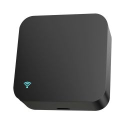
    Chips I'm trying to flash: BK7231N (Tuya USB Smart Adapter) and BK7231T (Tuya S06 IR Remote)
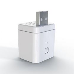
    White Tuya smart USB adapter with a USB plug
    Black smart USB adapter with a WiFi icon in the lower left corner.

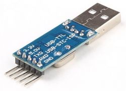
    USB UART adapter I've tried: CH341T and PL2303
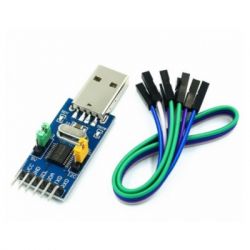
    USB UART adapter with colored wires. USB-TTL adapter with visible pins and TXD, RXD labels.

    Power supply: Either directly from CH341T UART adapter or independent AMS1117 module set to 3.3v

    I checked all solder joints with multimeter and made sure that the connection is secure and RX/TX of UART adapter is connected to TX/RX of BK7231 chips.

    When GUI Flash Tool asks me to reset the device by either power cycling it or shorting CEN to GND, I do as instructed and I can see that the device is reset by power led turning off and on. However the tool doesn't detect it and keeps displaying 'Getting Bus' indefinitely even though I reset the device multiple times. I tried different baud rates which didn't work. I tried ltchiptool which failed to connect, too. What could be the problem here?
  • ADVERTISEMENT
  • #2 20746074
    p.kaczmarek2
    Moderator Smart Home
    Does the same happen if you try to use bkWriter 1.60 for BK7231T flash?

    Have you tried swapping RX and TX?

    Do you keep the cables short?

    How your setup looks like?
    Helpful post? Buy me a coffee.
  • #3 20746140
    223_38
    Level 2  
    Yes, I tried bkwriter with BK7231T chip, which just counted up to 15 seconds and then displayed 'Failed'.

    I tried swapping TX and RX which didn't help.

    I think my cables are as short as possible, being less than 20 centimeters from solder pads to UART adapter.

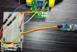
    Programming setup with a breadboard, BK7231T microcontroller, and UART adapter.

    My setup roughly looks like this.
  • #4 20746244
    p.kaczmarek2
    Moderator Smart Home
    Maybe something is connected to RX or TX of BK? Check your board. Maybe they use this pin for a button, or for a LED or something?
    Helpful post? Buy me a coffee.
  • ADVERTISEMENT
  • #5 20746489
    223_38
    Level 2  

    While there is a reset button and multiple LEDs on the board, I'm not sure if the TX and RX pads are connected to something else than the module.

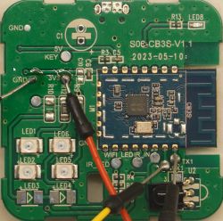
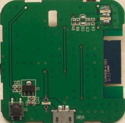
    However, my PCB is at least externally the same as the one described in this thread with the only difference being the date stenciled on my board is slightly later - May 2023 instead of December 2022 - and the BK7231 module of my device is WB3S instead of CB3S. Since that device did not require desoldering of the module, I don't think other parts on the board are the cause.

    In the case of the USB adapter, the board is exactly the same as this one, including the letters.
  • #6 21015125
    mrt724
    Level 3  

    Any chance you solved this issue I'm having exactly the same problem
  • ADVERTISEMENT
  • #7 21015137
    p.kaczmarek2
    Moderator Smart Home
    Pleace provide a high quality photo of the PCB. I think that RX or TX may be used for some other purpose on this board.

    We have already experienced similiar issue - the Smart Switch in this video was not flashable because of the capacitor on the board, so we had to remove this capacitor before flashing:


    Watch the full video. That proves that if there is something on RX/TX, flashing may fail...
    Helpful post? Buy me a coffee.
  • #8 21015301
    mrt724
    Level 3  

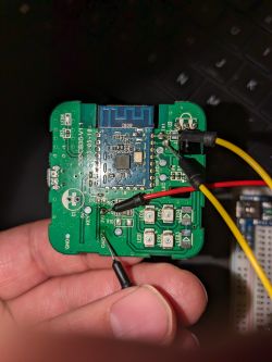
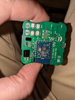
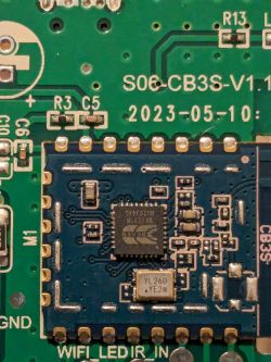
    Thanks for looking into this. Here is my pcb.

    Circuit board held in hand with connected wires. A person holding a printed circuit board with various electronic components. Close-up of a printed circuit board with visible electronic components.
  • #9 21015525
    p.kaczmarek2
    Moderator Smart Home
    Well, I must admit, I don't see much on this PCB. I am unable to tell at the moment whether RX/TX are connected somewhere futher.

    Do you have a multimeter, can you investigate?

    Or maybe are you able to desolder that CB3S module? I can give you some hints how to do that.

    Or maybe you are indeed making some kind of beginner mistake when it comes to flashing... idk, maybe the capacitor on the board is too large to do power off/on cycle and needs to be removed?
    Helpful post? Buy me a coffee.
  • ADVERTISEMENT
  • #10 21016350
    mrt724
    Level 3  
    Thanks @p.kaczmarek2 I appreciate you looking at this. Let me try to answer some of your questions, provide a little more detail and higher resolution images.

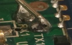
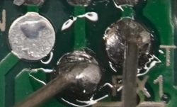
    Looking closely at the PCB I don't believe TX/RX go past the solder points and thus not are connected to anything else:
    Close-up of a damaged circuit board with visible solder points labeled RX1 and TX1.
    Close-up of solder points and traces on a circuit board with TX and RX markings visible.

    I do have a multimeter and if I know what I am checking I could probably identify it, but have lack of knowledge to know what I should check myself, other than ... are grounds connected, what's the voltage on 3v3, etc.

    Desoldering a full module, is probably a little above my skill level, although I saw another person replaced the beken with an esp and thought that was interesting.

    I definitely could be making a newbie mistake.
    I'm happy to describe or answer any questions you think would be helpful.
    1. The UART/USB is identified on my pc using device manager, then I use that port in either flashing tool.
    I have tried baud rates of 115200 and 921600.
    2. I am using a ESP8266 as pass through UART, tried doing the same with ESP32 dev board. This appears to be a well documented approach without a separate USB/UART module.
    (wiring up as follows):
    - ESP EN/RST pin set to GND (to keep the on board esp off)
    - ESP TX -> S06 RX (Tried it swapped)
    - ESP RX -> S06 TX (Tried it swapped)
    - ESP 3V3 -> S06 3V3
    - ESP GND -> S06 GND

    Easy UART Flasher interface with selected COM port and baud rate settings.
    A circuit board with a mounted CB3S module and connected wires.
    View of a printed circuit board with electronic components, including a button, USB socket, and several SMD components.
  • #11 21024059
    223_38
    Level 2  

    >>21015125

    Unfortunately, no. I had to give up and move on to Zigbee devices. While options are more limited it's more hassle-free and works well. Maybe I'll try some other devices later but for now I'm settling with Zigbee.
  • #12 21025274
    mrt724
    Level 3  

    I managed to get the flashing tool to recognize the device finally and it appears that I'm getting OpenBK to flash. For anyone who is running into this issue I solved it with these three tips,
    1. Try swapping tx/rx
    2. Make sure you have a separate 3.3v power supply.
    3. When doing GND to RST repeat every couple of seconds until one of them triggers at the right time.

    NEW ISSUE: The Access Point isn't appearing after flashing.
  • #13 21025290
    divadiow
    Level 34  
    Whenever the AP dies for me, and safe mode definitely doesn't bring it up, I blast a sequence of - erase all, restore rf partition, flash original factory firmware. Check RF works again by pairing with Tuya app. Start again to free from cloud with OBK.

    I think some combination, maybe twice over with reboots in between, has always worked eventually to revive it.
  • #14 21025446
    p.kaczmarek2
    Moderator Smart Home
    What does the TX2 log output say?
    I flashed hundreds of devices and haven't managed to get "no access point" issue so far...
    Helpful post? Buy me a coffee.
  • #15 21025932
    mrt724
    Level 3  

    >>21025290

    So.... I think my original firmware got overwritten by a second flash in the backups folder. Is that something I can find?

    Also, is there any way to have logs sent to TX2 as I don't have a second UART.
  • #16 21026603
    p.kaczmarek2
    Moderator Smart Home
    mrt724 wrote:

    So.... I think my original firmware got overwritten by a second flash in the backups folder. Is that something I can find?

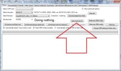
    To the best of my knowledge it is not possible to overwrite the firmware backup file taken by BK7231 easy UART flasher. This is because each created backup file has a current date/time string in the name and backup procedure takes so time so there is no chance that a backup file will be overwritten. Are you really sure that your backup file is not present? Use "open backups dir" button and check the files:
    Screenshot of the BK7231 Easy UART Flasher application with the Open backups dir button highlighted.

    mrt724 wrote:

    Also, is there any way to have logs sent to TX2 as I don't have a second UART.

    Logs are always by default sent via TX2 (UART 2 TX port). The UART 1 port (TX1/RX1) is used for flashing. You don't need two separate USB to UART converters for that, you can just temorary disconnect your wire from TX1 and connect it to TX2 in order to check the debug log output.
    Alternatively, after flashing OpenBeken, you can configure it to use TX1 as debug log output. See our autoexec examples for more details:
    https://github.com/openshwprojects/OpenBK7231T_App/blob/main/docs/autoexecExamples.md
    Search for "logport" command in the samples above.
    Helpful post? Buy me a coffee.

Topic summary

The discussion revolves around the challenges faced by a user attempting to flash Beken BK7231N and BK7231T chips using CH341T and PL2303 UART adapters. The user reports unsuccessful attempts despite following tutorial videos, checking connections, and ensuring proper power supply. Responses suggest troubleshooting steps such as using bkWriter, swapping RX and TX connections, and checking for unintended connections on the PCB. The user later manages to get the flashing tool to recognize the device and successfully flash OpenBK by ensuring a separate 3.3V power supply and using a specific reset method. However, they encounter a new issue where the access point does not appear post-flashing, prompting further troubleshooting advice regarding firmware restoration and log output.
Summary generated by the language model.
ADVERTISEMENT