Hello,
this product is the S06 Version of the IR Blaster. For the S06Pro Version I found this Teardown article:
https://www.elektroda.com/rtvforum/topic3926882.html#20238985
Which is similar, has the same package and case but a different pcb and another Chip. I didnt found this product on the official list so I took it on me to make a little post for someone who had the same questions like me.
![Teardown, flashing and configuration for Smart Tuya IR Blaster S06 [CB3S] Teardown, flashing and configuration for Smart Tuya IR Blaster S06 [CB3S]](https://obrazki.elektroda.pl/6078036200_1677795924_thumb.jpg)
![Teardown, flashing and configuration for Smart Tuya IR Blaster S06 [CB3S] Teardown, flashing and configuration for Smart Tuya IR Blaster S06 [CB3S]](https://obrazki.elektroda.pl/3691285800_1677795931_thumb.jpg)
![Teardown, flashing and configuration for Smart Tuya IR Blaster S06 [CB3S] Teardown, flashing and configuration for Smart Tuya IR Blaster S06 [CB3S]](https://obrazki.elektroda.pl/8489019500_1677795940_thumb.jpg)
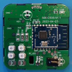
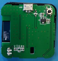
This IR one uses the CB3S chip. Here is the PCB
![Teardown, flashing and configuration for Smart Tuya IR Blaster S06 [CB3S] Teardown, flashing and configuration for Smart Tuya IR Blaster S06 [CB3S]](https://obrazki.elektroda.pl/9573042600_1677795927_thumb.jpg)
![Teardown, flashing and configuration for Smart Tuya IR Blaster S06 [CB3S] Teardown, flashing and configuration for Smart Tuya IR Blaster S06 [CB3S]](https://obrazki.elektroda.pl/2315281100_1677795930_thumb.jpg)
And here is the official Tuya Module Datasheet:![Teardown, flashing and configuration for Smart Tuya IR Blaster S06 [CB3S] Teardown, flashing and configuration for Smart Tuya IR Blaster S06 [CB3S]](https://obrazki.elektroda.pl/7329364400_1677797440_thumb.jpg)
I used the BK7231Flasher Tool to Flash the Chip with the OpenBK7231N Firmware. The Tool is very useful and even downloads the right file for you. Because this IR Blaster uses the CB3S Chip, you have to select BK7231N Type. After downloading the firmware I connected the Chip to my USB to TTL bridge. You can use any bridge (The Github guide of the tool was a good tutorial). It should have VCC on 3.3V. I soldered the wires onto the PCB on the right places, no need to go straight onto the chip.
VCC-> 3.3V
GND -> GND
RX -> TX1
TX -> RX1
(See colored Points in picture)
![Teardown, flashing and configuration for Smart Tuya IR Blaster S06 [CB3S] Teardown, flashing and configuration for Smart Tuya IR Blaster S06 [CB3S]](https://obrazki.elektroda.pl/7485033800_1677796863_thumb.jpg)
![Teardown, flashing and configuration for Smart Tuya IR Blaster S06 [CB3S] Teardown, flashing and configuration for Smart Tuya IR Blaster S06 [CB3S]](https://obrazki.elektroda.pl/4029797000_1677796870_thumb.jpg)
After starting the flash process I disconnected the VCC wire from the TTL Bridge and reconnected it, instead of shorting ground with the CEN pin. After Flashing it, it opened the Access Point and I could configure it on the webpage.
The Pin Configuration is this (This took the longest time to find out, by using the multimeter and Trial and Error):
IRRecv | P7 (PWM1)
IRSend | P26 (PWM5)
LED | P8 (PWM2)
Btn | P6 (PWM0)
I bought this as a zigbee version to connect with home assistant, but got delivered this wifi version. If you happen to have the same problem, you can use this transmitter with mqtt and home assistant. If you have questions about it feel free to ask.
this product is the S06 Version of the IR Blaster. For the S06Pro Version I found this Teardown article:
https://www.elektroda.com/rtvforum/topic3926882.html#20238985
Which is similar, has the same package and case but a different pcb and another Chip. I didnt found this product on the official list so I took it on me to make a little post for someone who had the same questions like me.
![Teardown, flashing and configuration for Smart Tuya IR Blaster S06 [CB3S] Teardown, flashing and configuration for Smart Tuya IR Blaster S06 [CB3S]](https://obrazki.elektroda.pl/6078036200_1677795924_thumb.jpg)
![Teardown, flashing and configuration for Smart Tuya IR Blaster S06 [CB3S] Teardown, flashing and configuration for Smart Tuya IR Blaster S06 [CB3S]](https://obrazki.elektroda.pl/3691285800_1677795931_thumb.jpg)
![Teardown, flashing and configuration for Smart Tuya IR Blaster S06 [CB3S] Teardown, flashing and configuration for Smart Tuya IR Blaster S06 [CB3S]](https://obrazki.elektroda.pl/8489019500_1677795940_thumb.jpg)
This IR one uses the CB3S chip. Here is the PCB
![Teardown, flashing and configuration for Smart Tuya IR Blaster S06 [CB3S] Teardown, flashing and configuration for Smart Tuya IR Blaster S06 [CB3S]](https://obrazki.elektroda.pl/9573042600_1677795927_thumb.jpg)
![Teardown, flashing and configuration for Smart Tuya IR Blaster S06 [CB3S] Teardown, flashing and configuration for Smart Tuya IR Blaster S06 [CB3S]](https://obrazki.elektroda.pl/2315281100_1677795930_thumb.jpg)
And here is the official Tuya Module Datasheet:
![Teardown, flashing and configuration for Smart Tuya IR Blaster S06 [CB3S] Teardown, flashing and configuration for Smart Tuya IR Blaster S06 [CB3S]](https://obrazki.elektroda.pl/7329364400_1677797440_thumb.jpg)
I used the BK7231Flasher Tool to Flash the Chip with the OpenBK7231N Firmware. The Tool is very useful and even downloads the right file for you. Because this IR Blaster uses the CB3S Chip, you have to select BK7231N Type. After downloading the firmware I connected the Chip to my USB to TTL bridge. You can use any bridge (The Github guide of the tool was a good tutorial). It should have VCC on 3.3V. I soldered the wires onto the PCB on the right places, no need to go straight onto the chip.
VCC-> 3.3V
GND -> GND
RX -> TX1
TX -> RX1
(See colored Points in picture)
![Teardown, flashing and configuration for Smart Tuya IR Blaster S06 [CB3S] Teardown, flashing and configuration for Smart Tuya IR Blaster S06 [CB3S]](https://obrazki.elektroda.pl/7485033800_1677796863_thumb.jpg)
![Teardown, flashing and configuration for Smart Tuya IR Blaster S06 [CB3S] Teardown, flashing and configuration for Smart Tuya IR Blaster S06 [CB3S]](https://obrazki.elektroda.pl/4029797000_1677796870_thumb.jpg)
After starting the flash process I disconnected the VCC wire from the TTL Bridge and reconnected it, instead of shorting ground with the CEN pin. After Flashing it, it opened the Access Point and I could configure it on the webpage.
The Pin Configuration is this (This took the longest time to find out, by using the multimeter and Trial and Error):
IRRecv | P7 (PWM1)
IRSend | P26 (PWM5)
LED | P8 (PWM2)
Btn | P6 (PWM0)
I bought this as a zigbee version to connect with home assistant, but got delivered this wifi version. If you happen to have the same problem, you can use this transmitter with mqtt and home assistant. If you have questions about it feel free to ask.
Cool? Ranking DIY


![Teardown, flashing and configuration for Smart Tuya IR Blaster S06 [CB3S] Teardown, flashing and configuration for Smart Tuya IR Blaster S06 [CB3S]](https://obrazki.elektroda.pl/5454636600_1680209358_thumb.jpg)
![Teardown, flashing and configuration for Smart Tuya IR Blaster S06 [CB3S] Teardown, flashing and configuration for Smart Tuya IR Blaster S06 [CB3S]](https://obrazki.elektroda.pl/9597187000_1680209358_thumb.jpg)
![Teardown, flashing and configuration for Smart Tuya IR Blaster S06 [CB3S] Teardown, flashing and configuration for Smart Tuya IR Blaster S06 [CB3S]](https://obrazki.elektroda.pl/2453695400_1680209359_thumb.jpg)
![Teardown, flashing and configuration for Smart Tuya IR Blaster S06 [CB3S] Teardown, flashing and configuration for Smart Tuya IR Blaster S06 [CB3S]](https://obrazki.elektroda.pl/2379154400_1680209359_thumb.jpg)
![Teardown, flashing and configuration for Smart Tuya IR Blaster S06 [CB3S] Teardown, flashing and configuration for Smart Tuya IR Blaster S06 [CB3S]](https://obrazki.elektroda.pl/6254316200_1680209357_thumb.jpg)
![Teardown, flashing and configuration for Smart Tuya IR Blaster S06 [CB3S] Teardown, flashing and configuration for Smart Tuya IR Blaster S06 [CB3S]](https://obrazki.elektroda.pl/2151562200_1680209357_thumb.jpg)
![Teardown, flashing and configuration for Smart Tuya IR Blaster S06 [CB3S] Teardown, flashing and configuration for Smart Tuya IR Blaster S06 [CB3S]](https://obrazki.elektroda.pl/9305258500_1681736372_thumb.jpg)
![Teardown, flashing and configuration for Smart Tuya IR Blaster S06 [CB3S] Teardown, flashing and configuration for Smart Tuya IR Blaster S06 [CB3S]](https://obrazki.elektroda.pl/8454463900_1682066308_thumb.jpg)
![Teardown, flashing and configuration for Smart Tuya IR Blaster S06 [CB3S] Teardown, flashing and configuration for Smart Tuya IR Blaster S06 [CB3S]](https://obrazki.elektroda.pl/4280752500_1682066359_thumb.jpg)
![Teardown, flashing and configuration for Smart Tuya IR Blaster S06 [CB3S] Teardown, flashing and configuration for Smart Tuya IR Blaster S06 [CB3S]](https://obrazki.elektroda.pl/6201363100_1682071020_thumb.jpg)
![Teardown, flashing and configuration for Smart Tuya IR Blaster S06 [CB3S] Teardown, flashing and configuration for Smart Tuya IR Blaster S06 [CB3S]](https://obrazki.elektroda.pl/7542191100_1682234812_thumb.jpg)
![Teardown, flashing and configuration for Smart Tuya IR Blaster S06 [CB3S] Teardown, flashing and configuration for Smart Tuya IR Blaster S06 [CB3S]](https://obrazki.elektroda.pl/8614231000_1682235011_thumb.jpg)

