logo elektroda
logo elektroda
X
logo elektroda

BK7231T/BK7231N WiFi, MQTT, template and IP configuration at flash time via UART - OpenBeken flasher

p.kaczmarek2 9225 11
ADVERTISEMENT
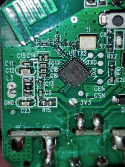
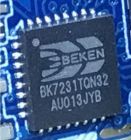
  • Close-up view of BK7231 chip on a circuit board.
    BK7231GUIFlashTool allows you to configure OpenBeken at the flash time - there is no need for Open Access Point configuration, everything can be done on your PC. Here I will show you how to do it step by step.

    Why?
    The usual BK7231 flashing and configuration process is similar to Tasmota/Esphome/Etc. First you flash firmware via UART (there is also a wireless option, but this topic refers to wired method), then software creates open access point where you connect and configure your device.
    However, there is an alternate way to do it in OpenBeken.
    With OpenBeken, you can configure OBK at the flash time - that way you can read and write OBK config via UART.
    This lets you skip the "open access point" part and enter your WiFi data from your PC.
    This has several advantages, including:
    - it is quicker than open access point method
    - it does not disconnect you from internet, if you connect to web via the same WiFi you'd use for OBK
    - if your device is battery powered, there is no risk of device going back to sleep
    - this can help you recover from potential wrong configuration and boot problems
    - this can be one of the ways of automatic GPIO config (but we'll cover it another time)
    - soon this can help you batch-convert devices

    Step 1: Flash your device via UART
    Just do the usual process of programming BK7231, see our readme for more information:
    https://github.com/openshwprojects/BK7231GUIFlashTool
    You can also watch tutorials on our YT channel:
    https://www.youtube.com/@elektrodacom

    Step 2: Once OBK is flashed, do the OBK config read
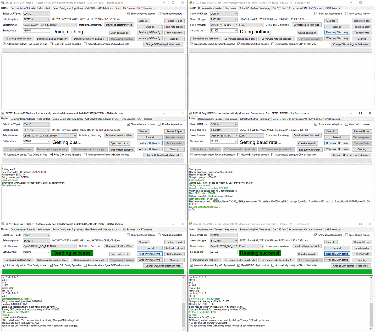
    Click "Read only OBK config" to read the OBK config from device flash to the application memory via UART:
    BK7231 Easy UART Flasher interface with configuration and flashing options.
    Do the CEN reset or power cycle if required. If you want to have automatic restart while using BK7231GUIFlashTool flash tool, please enable flag 31 ("enable UART command line")

    Step 3: Modify OBK config
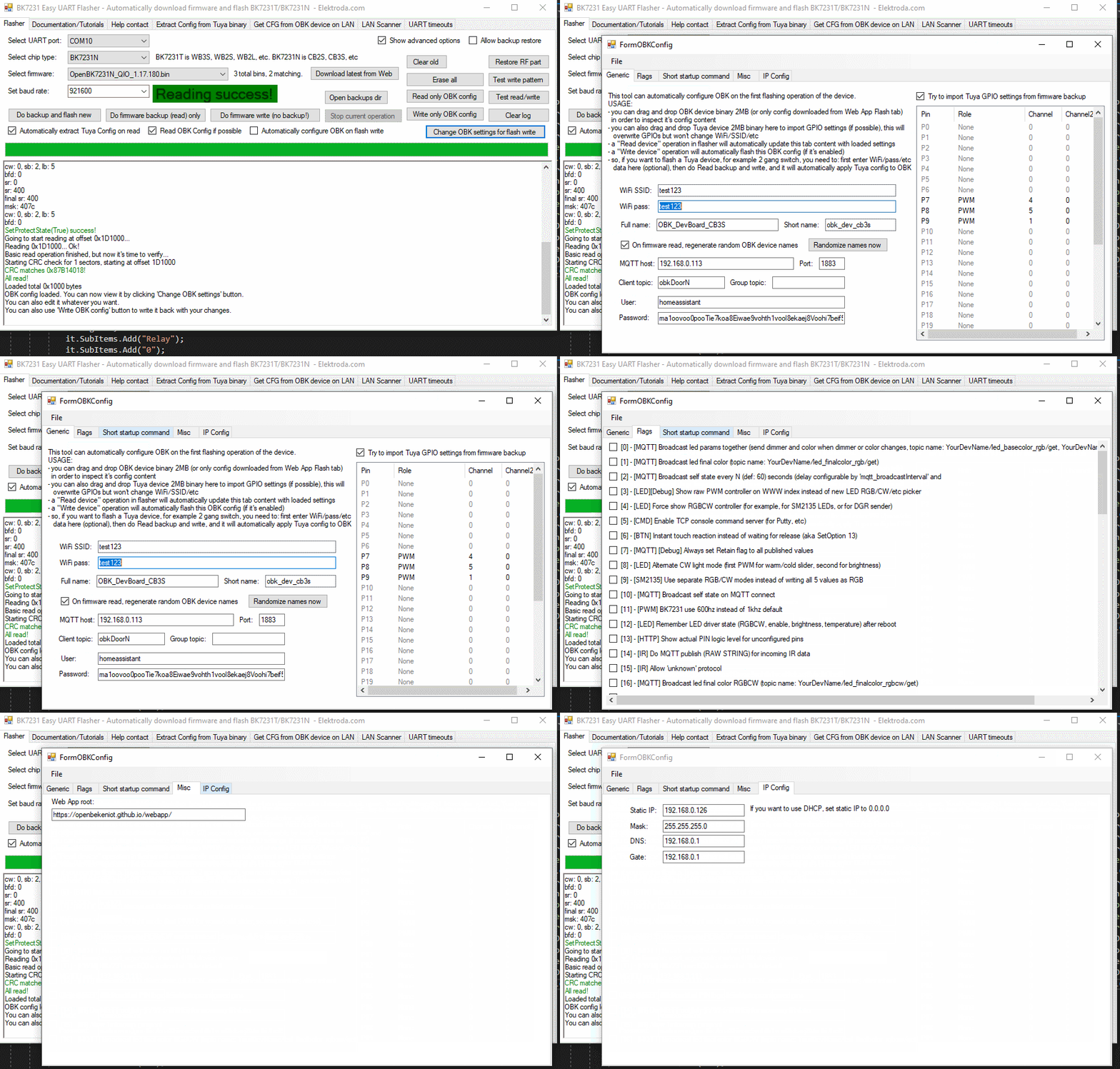
    Click "Change OBK settings" and change settings to suit your needs:
    BK7231GUIFlashTool software interface displaying configuration read success.
    Here you can enter your WiFi data, IP settings, MQTT settings, flags, and even a short startup command. More options will be added soon.

    Step 4: Save back OBK config
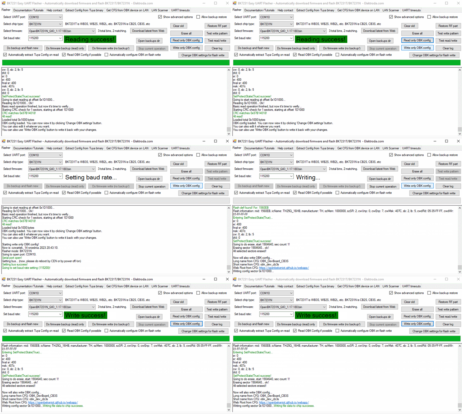
    Now, press "Write only OBK config" and do power cycle if needed (if UART command line is enabled, it will not be needed):
    BK7231GUIFlashTool interface with successful OBK configuration read.


    Summary
    That's all! This way you can configure your OBK without even creating an access point, so there is also no potential security risk of someone else accessing it at the config time. This can be very hand for many users. Let me know what you think about this option.
    Soon I will also cover more options of BK7231GUIFlashTool , so stay tuned for another topic! If you have any feature request, feel free to ask.

    Cool? Ranking DIY
    Helpful post? Buy me a coffee.
    About Author
    p.kaczmarek2
    Moderator Smart Home
    Offline 
    p.kaczmarek2 wrote 11920 posts with rating 9984, helped 572 times. Been with us since 2014 year.
  • ADVERTISEMENT
  • #2 20804942
    Tony2k
    Level 5  
    I'm trying to flash a bk7231N smart switch but I have write fails. Changing baud rate only changes the sector at which the error occurs, this is the log:

    All selected sectors erased! Writing sector 0x00... ok! Writing sector 0x1000... ok! Writing sector 0x2000... ok! Writing sector 0x3000... ok! Writing sector 0x4000... ok! Writing sector 0x5000... ok! Writing sector 0x6000... ok! Writing sector 0x7000... ok! Writing sector 0x8000... ok! Writing sector 0x9000... ok! Writing sector 0xA000... ok! Writing sector 0xB000... ok! Writing sector 0xC000... ok! Writing sector 0xD000... ok! Writing sector 0xE000... ok! Writing sector 0xF000... ok! failed with serial.BytesToRead 1 (expected 15) The beginning of buffer in UART contains FF data. Writing sector 0x10000... Writing sector 65536 failed! Writing file data to chip failed.

    I tried also the change pc but it fails exactly at the same sectors, do you have any idea?
  • ADVERTISEMENT
  • #3 20805018
    p.kaczmarek2
    Moderator Smart Home
    You can try to shorten the wires to the programmer. You can also use old hid_download_py method:


    Which USB to UART dongle are you using?
    Helpful post? Buy me a coffee.
  • #4 20805031
    Tony2k
    Level 5  
    I use FT232 (probably not genuine). I'll try to shorten wires.
  • ADVERTISEMENT
  • #5 20805035
    p.kaczmarek2
    Moderator Smart Home
    And how do you power the device?

    You can also try to set longer delays in one of the tabs of BK7231 flasher
    Helpful post? Buy me a coffee.
  • #6 20805044
    Tony2k
    Level 5  
    I tried powering it both from FT232 and from the onboard power supply. Do you mean UART timeouts? I tried to set 10/10/5 but nothing.
  • #7 20809675
    Tony2k
    Level 5  
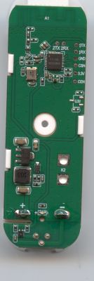
    @pkaczmarek262 could the problem be related to the MCU that is integrated on the mainboard and it's connected to the wifi module?

    Close-up of a circuit board with an integrated chip and electronic components.
  • #8 20809704
    p.kaczmarek2
    Moderator Smart Home
    It indeed seems that RXD trace is used for some other purpose. Can you check where it leads? Maybe you need to temporarily cut it, just like we did on our video tutorial:


    Helpful post? Buy me a coffee.
  • ADVERTISEMENT
  • #9 20809793
    Tony2k
    Level 5  
    I cutted the trace (it goes to the button, now led doesn't works) but nothing changed. I also tried so set delay to 50 and now flash ends but I have CRC fail.
  • #11 21096373
    p.kaczmarek2
    Moderator Smart Home
    Sure, here is a latest release, please check if it's ok:
    https://github.com/openshwprojects/BK7231GUIFlashTool
    What is the use case of custom offsets/lengths?

    PS: In general, please try to open requests on forum, as I am checking forum more often than Github
    Helpful post? Buy me a coffee.
  • #12 21096376
    divadiow
    Level 34  
    thank you.

    I can't recall most recent use, but when playing with flashing unknown or odd chips it's useful. I've used non-Easy Flasher tools in the past to achieve this. It's fine, most people won't need it I guess. A nice-to-have is all.

Topic summary

The discussion revolves around the flashing and configuration of BK7231N smart switches using the BK7231GUIFlashTool, which allows for configuration at flash time via UART, bypassing the need for an open access point. Users report issues with write failures during the flashing process, with suggestions including shortening wire lengths, adjusting power supply methods, and modifying UART timeouts. The conversation also touches on potential hardware issues related to the MCU and RXD trace connections. Additionally, there are requests for updates to the flashing tool and discussions on the utility of custom offsets for flashing unknown chips.
Summary generated by the language model.
ADVERTISEMENT