logo elektroda
logo elektroda
X
logo elektroda

First start with SiPEED M1S DOCK module - AI+IoT RTOS_Linux All-Round Module

p.kaczmarek2 3312 14
ADVERTISEMENT
Treść została przetłumaczona polish » english Zobacz oryginalną wersję tematu
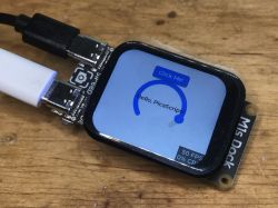
  • Sipeed M1s Dock module with connected USB cables and a display showing Hello, PicaScript!. I'd like to invite you to a hands-on demonstration and first steps with the Sipeed M1s Dock module with a 2MP camera with MIPI CSI interface and a 1.69-inch 280x240 capacitive touchscreen display for AIoT applications. The module was already briefly presented in the topic: Sipeed M1s and M0sense - inexpensive AI modules based on BL808 and BL702 so here I will focus on showing how it looks in practice.
    The board can be purchased for a little more than PLN 100:
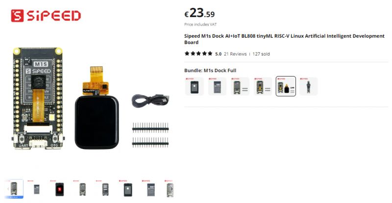
    Sipeed M1s Dock AI+IoT kit with display and camera module
    First, make sure that you choose a kit with a camera and a screen. It is easy to be fooled by a lower price, where in fact you buy, for example, the module or the case alone. It is necessary to check well what you order.
    What does the M1S offer?
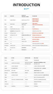
    Let's give voice to the specifications from the seller:
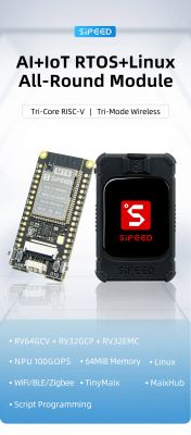
    First start with SiPEED M1S DOCK module - AI+IoT RTOS_Linux All-Round Module First start with SiPEED M1S DOCK module - AI+IoT RTOS_Linux All-Round Module First start with SiPEED M1S DOCK module - AI+IoT RTOS_Linux All-Round Module First start with SiPEED M1S DOCK module - AI+IoT RTOS_Linux All-Round Module First start with SiPEED M1S DOCK module - AI+IoT RTOS_Linux All-Round Module Inputs:
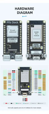
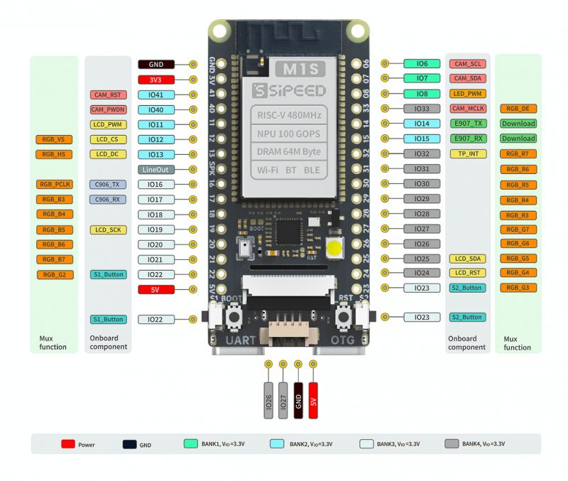
    Sipeed M1s Dock board with labeled pins.
    A housing can also be purchased, although mounting it requires moving the camera to the other side of the module:
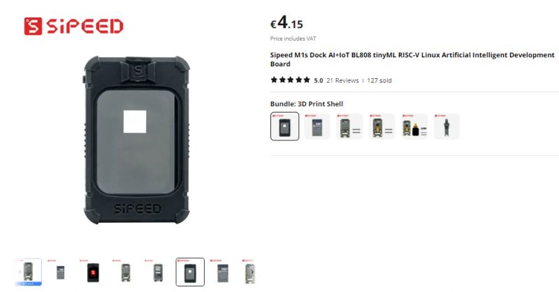
    Image of Sipeed M1s Dock module offer with price and thumbnails of various views.
    The basis of our work with this module will probably be the documentation from sipeed com:
    https://wiki.sipeed.com/hardware/en/maix/m1s/m1s_dock.html
    I also based my work on this material myself. Below is a description of my steps, along with my comments and experiences.

    First boot
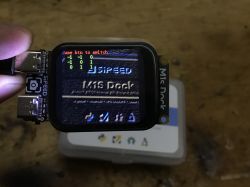
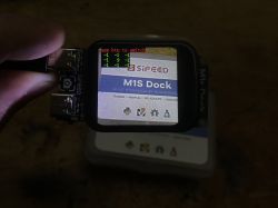
    Put power to the OTG port and press the RESET button. The board should wake up, the screen and camera will boot up.
    The delay from the camera is not noticeable, everything runs very smoothly:


    The screen also shows the status of the buttons, as a demonstration, they can change the value of the number in the upper right corner:


    Additionally, our computer will recognize the new USB device. This can be used to upload firmware for us.
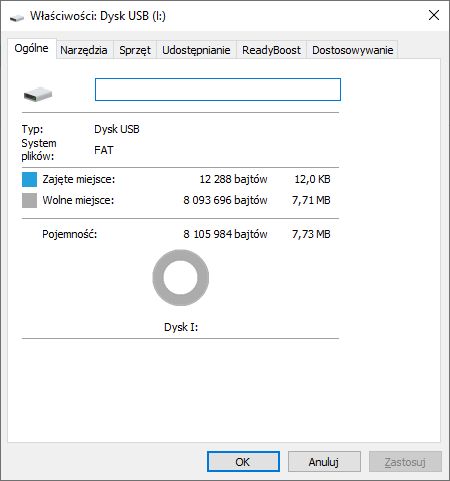
    USB drive properties window showing file system and capacity information.
    In the manufacturer's documentation, the USB drive shown here is 3.73MB, in mine the size is slightly larger. Do I have a newer version with more memory?
    Screenshot of the Devices and Drives window in Windows, showing a connected USB drive with a capacity of 7.73 MB.

    The second USB C slot offers access to the serial port. You need to select baud 2000000:
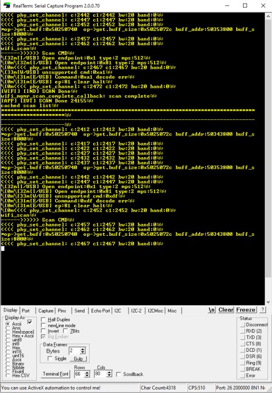
    Screenshot of RealTerm program with serial communication.
    And actually - to the serial ports, because there are two:
    Screenshot of software settings for serial port with baud rate of 2000000 and list of available ports.
    The first is the already shown log, the second is the command line.
    You can send commands there, for example help :
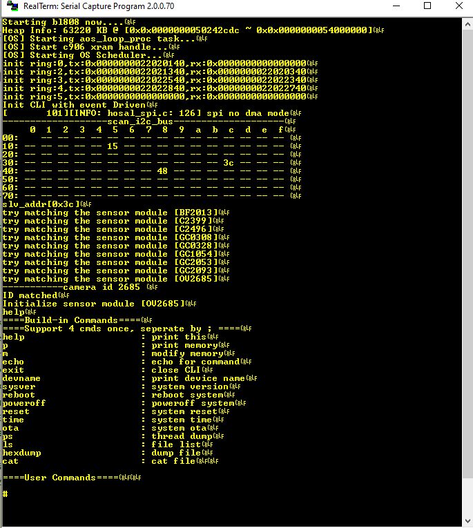
    RealTerm program interface displaying data in terminal mode.


    Demo lvgl_demo [/size]
    Let's now take a look at some examples from M1s_BL808_example. First, a graphics demo.
    LVGL (Light and Versatile Graphics Library) is a free open source library for drawing graphics.
    A compiled example is available here:
    https://dl.sipeed.com/shareURL/MAIX/M1s/M1s_Dock/7_Firmware/demo_bin/lvgl_demo
    To upload the batch, you need first put the board into the upload state .
    Really - just because the board is also visible as a flash device/memory while the demo is running, doesn't mean it will succeed in uploading something.
    Hold both side buttons and then press RESET, then release RESET and only then release the side buttons .
    Then drag the downloaded (or compiled by us) batch onto the mobile device:
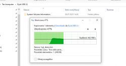
    File copying screen to USB drive.
    After a while, the board should boot itself. Here's the LVGL demo in action:


    At the end, a menu will be displayed where you can also test the touchscreen:


    Front-facing camera
    After purchase, you will receive the module received in such a way, that the camera "looks" in the same direction as the display. This makes testing difficult to some extent.
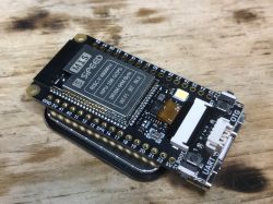
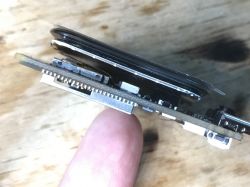
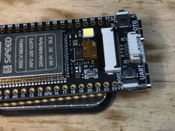
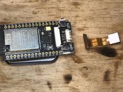
    The camera can be switched to the other side, as its ribbon goes through a slot in the PCB:
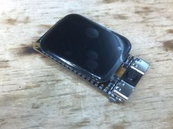
    Sipeed M1s Dock module with display and camera. Sipeed M1s Dock module on a wooden background. Sipeed M1s Dock module with screen and camera viewed from the side. First you need to unfasten the ribbon (on the other side of the connector you unfasten it):
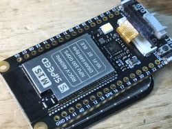
    Close-up of the Sipeed M1s Dock module with a camera and user interface. Sipeed M1s Dock module with ports and components on a PCB.
    Removed camera:
    Sipeed M1s Dock module with detached camera module
    The camera can be plugged in so that it will be on the other side of the module, but we can not reverse the ribbon, pins first (marked 1) of the ribbon must match pin 1 on the connector:
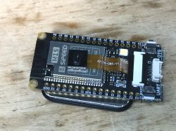
    Sipeed M1s Dock module with camera and headers on a wooden background

    . Image processing demo Another demo, image_processing_demo, demonstrates the ability to process images. The processing itself is quite simple, we use the buttons to select one of the predefined masks and so we can observe the effects:
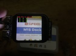
    Sipeed M1s Dock module with an active display. Sipeed M1s Dock module with display and camera in action Close-up of the Sipeed M1s Dock module with a 2MP camera and 1.69-inch display, showing interface graphics.
    [size=18] Character recognition demo? Now let's run the tinymaix_mnist_demo demo.
    TinyMaix is a small neural network inference library designed specifically for microcontrollers (TinyML), allowing you to run lightweight machine learning models on any single-chip microcomputer. I didn't have much luck with this demo. In theory, it's supposed to recognize numbers, but in my case it often limped to 8 or recognized incorrectly. I can show a screenshot from the manufacturer's documentation here for comparison:
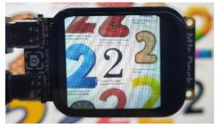
    Sipeed M1s Dock module with display and camera showcasing numbers Unlike me, on the other hand, it was.... hard, only perfect digits under perfect lighting are recognized:
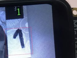
    Display showing the recognized digit 1
    With my painter's handwriting, the program confuses 1 with 7 and with 5 it does not cope at all:


    PikaScript language
    There is also a demo PikaScript . PikaScript is a cross-platform, powerful Python-based scripting language.
    After uploading the PikaScript demo, we can send this script to the board via the UART, line by line. Here's an example:
    arc = lv.arc(lv.scr_act())
    arc.set_end_angle(200)
    arc.set_size(150, 150)
    arc.center()
    

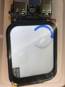
    Let's review how this script works step by step. The first line creates the arc/slider, here is the effect after execution:
    
    arc = lv.arc(lv.scr_act())
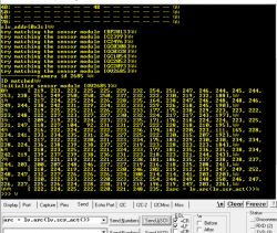
    

    Terminal interface displaying sensor module information. Sipeed M1s Dock with screen and USB-C ports
    The line with set_end_angle sets the position of the knob:
    
    arc.set_end_angle(200)
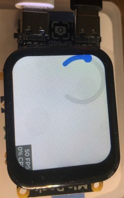
    
    Sipeed M1s Dock module with a screen displaying graphics on a 1.69-inch display.
    You can change the value of its argument, then the effect will be different:
    
    arc.set_end_angle(380)
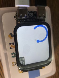
    
    Sipeed M1s Dock module with display and USB cables
    The center function, on the other hand, centers the object on the screen:
    
    arc.center()
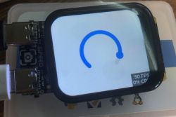
    

    Display with blue arc on Sipeed M1s Dock module.
    Let's try to do a little more. Maybe a script like this:
    
    # Create a screen
    scr = lv.scr_act()
    
    # Create a label widget
    label = lv.label(scr)
    label.set_text("Hello, PicaScript!")
    label.align(lv.ALIGN.CENTER, 0, 0)
    

    Result:
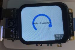
    Sipeed M1s Dock with display showing Hello, PicaScript!
    You can also create a button:
    
    # Create a button widget
    btn = lv.btn(scr)
    btn.align(lv.ALIGN.CENTER, 0, -20)
    label = lv.label(btn)
    label.set_text("Click Me!")
    

    Result:
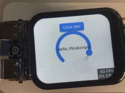
    Sipeed M1s Dock display with Hello, PicaScript! message and Click Me! button.
    I also tried to write a click event handler for the button in this language, but I haven't gotten it to work yet.

    Compiling source examples [/size] Compiling source examples[/b] 6fbd5ec
    On the main documentation page of the board there are also instructions for compiling example sources and full links to the SDK. I managed to compile them on a virtual machine with Ubuntu, there were no problems, therefore I do not describe it.
    Virtual machine console showing the completion of the compilation process.
    I also made an attempt to compile them on WSL, which is a "Linux environment on Windows", but I have not yet managed to get it working.


    Summary
    This was just a first look at this board. So far I like it.
    It is easy to upload programs, and the display and camera have satisfactory performance for me. I also didn't feel any image lag, and this also bodes well for future projects.
    In the next topic I'll try to compile, test and discuss other examples of it from the SDK, maybe I can also modify it a bit, such as making a simple watch on a touchscreen display.
    In addition, I plan to run an example of streaming video from a webcam to a PC (it is practically ready in the SDK) and experiment with TinyML.
    Meanwhile I will ask - do you have any experience with this board, do you see a potential use for it? Or do you think it is an unnecessary gadget and it is better to just reach for Raspberry? Feel free to discuss.

    Cool? Ranking DIY
    Helpful post? Buy me a coffee.
    Do you have a problem with Raspberry? Ask question. Visit our forum Raspberry.
    About Author
    p.kaczmarek2
    Moderator Smart Home
    Offline 
    p.kaczmarek2 wrote 11842 posts with rating 9938, helped 566 times. Been with us since 2014 year.
  • ADVERTISEMENT
  • #2 20803152
    chemik_16
    Level 26  
    Application - to read energy meters :) ESP and the like do not cope with OCR, this may have some chance. You have to catch the screen sequence change and then parse each one in turn. Only ofc it's too expensive, for 100zł you can already have rpi0 2w and camera. as if it was without a display ....
  • ADVERTISEMENT
  • #3 20803391
    p.kaczmarek2
    Moderator Smart Home
    OCR counter may be a good idea here. My test of their text detection demo was pretty rough. In a situation where we have one fixed font, it could probably work better. I'll have to try how much their demo can be rewritten to read individual digits sequentially, especially since their position on the screen doesn't change then.
    Helpful post? Buy me a coffee.
  • ADVERTISEMENT
  • #4 20803415
    PiotrekD
    Level 13  
    Hello my dears :)
    application - maybe wearable jewelry and an early warning module for stepping in dog turds which are now everywhere, or alternatively as a module that triggers the flush in the toilet right after it falls down.... The question is what about the pattern, how to sit down to it with TinyML. Can this module definitely handle it? That is the question.
  • ADVERTISEMENT
  • #5 20803484
    p.kaczmarek2
    Moderator Smart Home
    A discussion of TinyML themes is planned, I don't know how much yet, but I intend to do that as well. For the moment, I am familiarizing myself with this board.
    Helpful post? Buy me a coffee.
  • #6 20804081
    maestro16s
    Level 10  
    Try, out of curiosity, to draw the digits more in the "American" way, i.e. one is a straight line, 6 and 9 just as the Brda, mn.in., has lit up
  • #7 20806420
    p.kaczmarek2
    Moderator Smart Home
    There will be a moment then I will check it.

    Meanwhile I continue to struggle with the board - I already want to flash both cores, and for this you need a BLDevCube.

    For now I have the following observations:
    - USB cable or its length matters, on one longer one at my place does not work.... the RESET button - it just doesn't reboot the board. Reality. I uploaded Hello World and I can see that there is no reboot.
    - the laptop itself (drivers???) also makes a difference, on mine with W10 the flashing interrupted at Shakehand or a bit further, and on the other one it went 100% smoothly....
    Here are the logs:
    
    [09:23:23.716] - serial type is bouffalo
    [09:23:23.766] - Open COM27 Success
    [09:23:26.795] - Close COM27 Success
    [09:23:26.798] - ========= Interface is Uart =========
    [09:23:26.804] - eflash loader bin is eflash_loader_auto.bin
    [09:23:26.806] - ========= chip flash id: ef4016 =========
    [09:23:26.815] - create partition.bin, pt_new is True
    [09:23:26.853] - Create bootheader using chips\bl808\img_create_iot\efuse_bootheader_cfg.ini
    [09:23:26.855] - Updating data according to 
    [09:23:26.862] - Created file len:352
    [09:23:26.867] - Create bootheader using chips\bl808\img_create_iot\efuse_bootheader_cfg.ini
    [09:23:26.867] - Updating data according to 
    [09:23:26.873] - Created file len:352
    [09:23:26.877] - Create efuse using chips\bl808\img_create_iot\efuse_bootheader_cfg.ini
    [09:23:26.879] - Updating data according to 
    [09:23:26.885] - Created file len:256
    [09:23:26.894] - ========= sp image create =========
    [09:23:26.900] - Image hash is b'4eb457bd0c25aa8b122384056d8bc80391228247cfe67ef6123ba1af3048ecb3'
    [09:23:26.901] - Hash ignored
    [09:23:26.901] - Header crc ignored
    [09:23:26.901] - Write flash img
    [09:23:26.908] - Encrypt efuse data
    [09:23:26.923] - Warning: factory file is not programed to flash
    [09:23:26.924] - ========= eflash loader config =========
    [09:23:26.924] - Image offset = 8192
    [09:23:26.989] - Version: eflash_loader_v2.4.7
    [09:23:26.989] - Program Start
    [09:23:26.990] - ========= eflash loader cmd arguments =========
    [09:23:26.991] - Config file: C:\Users\Admin\Downloads\BouffaloLabDevCube-v1.8.6\chips\bl808\eflash_loader/eflash_loader_cfg.ini
    [09:23:26.993] - serial port is COM27 (PROG)
    [09:23:26.993] - cpu_reset=False
    [09:23:26.993] - chiptype: bl808
    [09:23:26.993] - ========= Interface is uart =========
    [09:23:26.994] - com speed: 2000000
    [09:23:26.994] - Bootrom load
    [09:23:26.994] - ========= get_boot_info =========
    [09:23:26.994] - ========= image get bootinfo =========
    [09:23:27.103] - ack is
    [09:23:27.104] - Not ack OK
    [09:23:27.104] - result:
    [09:23:27.117] - default set DTR high
    [09:23:27.221] - usb serial port
    [09:23:27.273] - clean buf
    [09:23:27.285] - send sync
    [09:23:27.792] - ack is 6b5a5a5a5a5a5a5a5a5a5a5a5a5a5a5a5a5a5a5a5a5a5a5a5a5a5a5a5a5a5a5a5a5a5a5a5a5a5a5a5a5aeb7baecb7b5eff6b5a5a5a5a5a5a5a5a5a5a595a5a5a5a5a5a5a5a5a5a5a5a5a5a5a5a5a5a5a5a5a5a5a5a7a5a565a584a527a1a725a535b5a4bb794ea3ff06b5a5a5a5a5a5a5a5a5a5a5a5a5a5a5a5a5a5a5a5a5a5a5a5a5a5a5a5a5a5a5a5a5a5a5a5a5a5a5ada5a7a5a4a5212ad6b6af5721a7a7b5ac66b5a5a5a5a5a5a5a5a5a5a5a5a5a5a5afac3
    [09:23:27.826] - shake hand success
    [09:23:30.329] - ack is
    [09:23:30.329] - Not ack OK
    [09:23:30.331] - result:
    [09:23:30.331] - get_boot_info no ok
    [09:23:30.331] - clock para file: C:\Users\Admin\Downloads\BouffaloLabDevCube-v1.8.6\chips/bl808/efuse_bootheader/clock_para.bin
    [09:23:30.332] - change bdrate: 2000000
    [09:23:30.332] - Clock PLL set
    [09:23:30.332] - clock para:
    [09:23:30.332] - 5043464707040000030103000102000201010001010101010a894b86
    [09:23:30.336] - FL5a6b unknown
    [09:23:30.336] - Retry
    [09:23:30.336] - FL5a1a unknown
    [09:23:30.336] - Retry
    [09:23:30.338] - FL6b62 unknown
    [09:23:30.338] - Retry
    [09:23:30.338] - FL1b56 unknown
    [09:23:30.338] - ErrorCode: 000C, ErrorMsg: BFLB SET CLOCK PLL FAIL
    [09:23:30.342] - pll set fail!!
    [09:23:30.342] - Burn Retry
    [09:23:30.342] - 0
    [09:23:30.342] - Burn return with retry fail
    [09:25:10.042] - ========= Interface is Uart =========
    [09:25:10.058] - eflash loader bin is eflash_loader_auto.bin
    [09:25:10.061] - ========= chip flash id: ef4016 =========
    [09:25:10.068] - create partition.bin, pt_new is True
    [09:25:10.103] - Create bootheader using chips\bl808\img_create_iot\efuse_bootheader_cfg.ini
    [09:25:10.105] - Updating data according to 
    [09:25:10.111] - Created file len:352
    [09:25:10.118] - Create bootheader using chips\bl808\img_create_iot\efuse_bootheader_cfg.ini
    [09:25:10.119] - Updating data according to 
    [09:25:10.125] - Created file len:352
    [09:25:10.129] - Create efuse using chips\bl808\img_create_iot\efuse_bootheader_cfg.ini
    [09:25:10.132] - Updating data according to 
    [09:25:10.138] - Created file len:256
    [09:25:10.147] - ========= sp image create =========
    [09:25:10.154] - Image hash is b'4eb457bd0c25aa8b122384056d8bc80391228247cfe67ef6123ba1af3048ecb3'
    [09:25:10.154] - Hash ignored
    [09:25:10.154] - Header crc ignored
    [09:25:10.155] - Write flash img
    [09:25:10.159] - Encrypt efuse data
    [09:25:10.213] - Create bootheader using chips\bl808\img_create_iot\efuse_bootheader_cfg.ini
    [09:25:10.214] - Updating data according to 
    [09:25:10.219] - Created file len:352
    [09:25:10.226] - Create bootheader using chips\bl808\img_create_iot\efuse_bootheader_cfg.ini
    [09:25:10.226] - Updating data according to 
    [09:25:10.232] - Created file len:352
    [09:25:10.236] - Create efuse using chips\bl808\img_create_iot\efuse_bootheader_cfg.ini
    [09:25:10.238] - Updating data according to 
    [09:25:10.243] - Created file len:256
    [09:25:10.255] - ========= sp image create =========
    [09:25:10.282] - Image hash is b'911b855d888c83ba53c63571beea888f19835c98fb861701102aceb126089227'
    [09:25:10.283] - Hash ignored
    [09:25:10.283] - Header crc ignored
    [09:25:10.283] - Write flash img
    [09:25:10.288] - Encrypt efuse data
    [09:25:10.292] - FW Header is 352, 3744 still needed
    [09:25:10.295] - FW OTA bin header is Done. Len is 4096
    [09:25:10.327] - BL60X_OTA_Ver1.0
    [09:25:10.362] - FW OTA bin is Done. Len is 193792
    [09:25:10.499] - OTA XZ file len = 71288
    [09:25:10.500] - Partiton len = 0
    [09:25:10.502] - Warn: fw1 xz bin size is overflow with partition table, don't create ota bin
    [09:25:10.502] - Warning: remove OTA files
    [09:25:10.503] - FW OTA xz is Done
    [09:25:10.540] - Create bootheader using chips\bl808\img_create_iot\efuse_bootheader_cfg.ini
    [09:25:10.541] - Updating data according to 
    [09:25:10.546] - Created file len:352
    [09:25:10.554] - Create bootheader using chips\bl808\img_create_iot\efuse_bootheader_cfg.ini
    [09:25:10.556] - Updating data according to 
    [09:25:10.563] - Created file len:352
    [09:25:10.566] - Create efuse using chips\bl808\img_create_iot\efuse_bootheader_cfg.ini
    [09:25:10.567] - Updating data according to 
    [09:25:10.572] - Created file len:256
    [09:25:10.581] - ========= sp image create =========
    [09:25:10.631] - Image hash is b'4a08929a7e7bbd559c1d4e81cb0537f12475ec43c8fabcb118c0e0aaab105352'
    [09:25:10.632] - Hash ignored
    [09:25:10.632] - Header crc ignored
    [09:25:10.632] - Write flash img
    [09:25:10.639] - Encrypt efuse data
    [09:25:10.641] - Warning: factory file is not programed to flash
    [09:25:10.643] - ========= eflash loader config =========
    [09:25:10.644] - Image offset = 8192
    [09:25:10.877] - Version: eflash_loader_v2.4.7
    [09:25:10.879] - Program Start
    [09:25:10.879] - ========= eflash loader cmd arguments =========
    [09:25:10.879] - Config file: C:\Users\Admin\Downloads\BouffaloLabDevCube-v1.8.6\chips\bl808\eflash_loader/eflash_loader_cfg.ini
    [09:25:10.881] - serial port is COM27 (PROG)
    [09:25:10.881] - cpu_reset=False
    [09:25:10.881] - chiptype: bl808
    [09:25:10.881] - ========= Interface is uart =========
    [09:25:10.881] - com speed: 2000000
    [09:25:10.882] - Bootrom load
    [09:25:10.882] - ========= get_boot_info =========
    [09:25:10.882] - ========= image get bootinfo =========
    [09:25:10.994] - ack is
    [09:25:10.995] - Not ack OK
    [09:25:10.995] - result:
    [09:25:11.006] - default set DTR high
    [09:25:11.119] - usb serial port
    [09:25:11.183] - clean buf
    [09:25:11.187] - send sync
    [09:25:11.709] - ack is 6b5a5a5a5a5a5a5a5a5a5a5a5a5a5a5adadecb7b5ed77b5ed77b5ed77b5ed77bded77bdecbfb5b5010633710af5a5a5a5a7a16165a5a5a5a5a5a5ada7bdecb7b5ed77bdecb7bde7b5ed77b5ad77b5ecb7b5ed77b5ed77b5ecb7b5ecb7b5ecb7b5ed77f5ed77b5ecb7bdecb7bde577b5ed77bded77bdad77b5ecb7b5fd77bdacb7bde7b5ecb7bdeea9a12e1af43535a5a5ada122c5b4a5a5a5a5a5a5aaed77bded67bdeeb7b5e577b5ed77b5ed77b5acb7b2fd77b5ed77b5ed77b5ecb7b5ed77bdecb7bdecb7bdedb7bded77bdecb7bde4bf6deeb7b5ed77b5e577b5e7fded6f27b5ed77f5ed77b5eb66d437be1af43535a5a5a7a3e12525a5a5a5a5a5ada7b5ed77b5ed77bded77bdecb7bdedb7b5ecb7bded77b5efdc3
    [09:25:11.756] - shake hand success
    [09:25:14.262] - ack is
    [09:25:14.263] - Not ack OK
    [09:25:14.263] - result:
    [09:25:14.263] - get_boot_info no ok
    [09:25:14.263] - clock para file: C:\Users\Admin\Downloads\BouffaloLabDevCube-v1.8.6\chips/bl808/efuse_bootheader/clock_para.bin
    [09:25:14.267] - change bdrate: 2000000
    [09:25:14.267] - Clock PLL set
    [09:25:14.267] - clock para:
    [09:25:14.268] - 5043464707040000030103000102000201010001010101010a894b86
    [09:25:16.271] - ack is
    [09:25:16.271] - Retry
    [09:25:18.274] - ack is
    [09:25:18.274] - Retry
    [09:25:20.277] - ack is
    [09:25:20.277] - Retry
    [09:25:22.279] - ack is
    [09:25:22.279] - ErrorCode: 000C, ErrorMsg: BFLB SET CLOCK PLL FAIL
    [09:25:22.280] - pll set fail!!
    [09:25:22.280] - Burn Retry
    [09:25:22.280] - 0
    [09:25:22.280] - Burn return with retry fail
    
    I don't know why this is the case yet, but I will update the topic.
    Helpful post? Buy me a coffee.
  • #8 20809413
    p.kaczmarek2
    Moderator Smart Home
    The problem previously described I did not solve, I still do not know why on one of my W10 machines it is impossible to flash this BL808, and on the other it is possible....

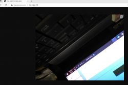
    But I have progress with the camera - I managed to run a demo of streaming video from the camera to the server on the PC via TCP, and then I was able to modify it so that the server is put on the board itself, and we can connect to it from the browser. Very fun, details coming soon to the forum:
    Photo showing a laptop keyboard and screen, partially visible in a browser at IP address 192.168.0.155. Maybe I will also open a pull request to the manufacturer examples to add my mini-server there.
    Helpful post? Buy me a coffee.
  • #9 20810176
    gulson
    System Administrator
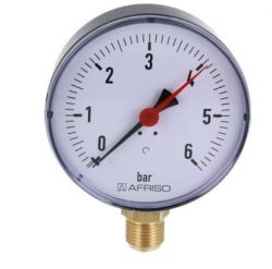
    All in all, I wonder if it would be possible to teach these boards to read various indicators in plants or at nodes:
    Traditional pressure gauge with a white dial and red needle, showing pressure up to 6 bar.
    All in all, these could be interesting monitoring devices, they would immediately send measurements via GSM.
    And there is no interference to the measuring devices themselves.

    Counters, gauges, lights, colors, switch status, etc.
  • #10 20812611
    gulson
    System Administrator
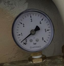
    How about adding Vision ChatGPT to read the indication of industrial equipment? A bit of overkill, but not sure if you can learn any other way at this point.
    @ElektrodaBot write what indication you see on the pressure gauge.
    Pressure gauge with a needle indicating 0.9 bar.
  • #11 20812618
    gulson
    System Administrator
    OK I take back the idea, you need to create something custom and dedicated to the given sensors, sensors or meters. How about this very board?
  • #13 20812888
    p.kaczmarek2
    Moderator Smart Home
    @chemik_16 good suggestion, I will try it out and maybe one day on the forum I will describe it
    Helpful post? Buy me a coffee.
  • #14 20816134
    arti4-92
    Level 17  
    Ever since I found out about this chip I was wondering how is the issue of HW documetance, i.e. dma and audio codecs. Could you tell me if getting the documentation is a big problem? And does it even allow you to write your own drivers for dma or codecs?

Topic summary

The discussion revolves around the SiPEED M1S Dock module, which features a 2MP camera with MIPI CSI interface and a 1.69-inch capacitive touchscreen, aimed at AIoT applications. Users explore various applications, including energy meter reading using OCR, wearable technology, and monitoring devices for industrial indicators. Challenges with flashing the module and USB connectivity issues are noted, alongside successful demonstrations of video streaming from the camera. The potential for integrating TinyML and custom sensor solutions is also discussed, highlighting the need for specific drivers and documentation for hardware components.
Summary generated by the language model.
ADVERTISEMENT