Elektroda.com
Elektroda.com
X

DDS function generator set for assembly, commissioning and tests

TechEkspert 14121 29
This content has been translated flag-pl » flag-en View the original version here.
  • DDS function generator set for assembly, commissioning and tests
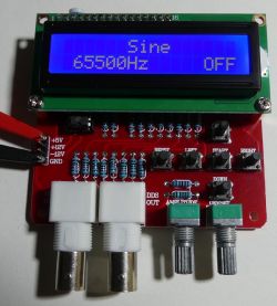
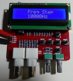
    Soon, the DDS generator will appear on elektroda.pl in the form of a mounting kit. The DDS generator allows for the production of 1,2,4,8MHz square signals and signals with a frequency adjustable up to 65KHz, among others with the shapes: sine, rectangle, saw, triangle and noise. The device is equipped with an alphanumeric LCD display with backlight, control buttons and potentiometers for setting the amplitude and constant component of the output signal. Power required + 5V, + 12V, -12V.

    It is worth starting the assembly of the device with small elements (resistors, capacitors), through the IC sockets and the LCD connector. The assembly can be done similarly to the mini-scopes DSO138 . After the + 5V voltage is supplied, the display contrast should be set using the mounting potentiometer.
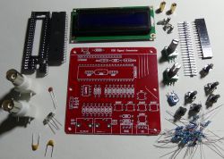
    DDS function generator set for assembly, commissioning and tests

    For the operation of the generator of "fast" square waveforms 1,2,4,8MHz it is enough to supply 5V, the HS output will show a square wave signal with an amplitude of ~ 5V. The device consumes ~ 30mA.
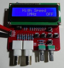
    DDS function generator set for assembly, commissioning and tests

    For the operation of the DDS generator (Direct Digital Synthesis), a symmetrical + 12V -12V power supply to the output operational amplifier is required. The current consumption in the symmetrical +/- 12V power lines is small (single milliamps), so you can use, for example, a small transformer with a split winding or one-way rectification + 12V stabilizers. You can also use DC / DC inductive or capacitive converters. The 8b DAC converter on the R-2R resistor ladder (10k and 20k) was used to generate the waveforms. Output amplitude adjustable to ~ 18-19Vpp.

    Use the buttons to select the waveform and frequency and start the waveform generation. The frequency cannot be changed during waveform generation. Stop signal generation and change frequency.
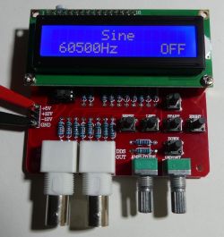
    DDS function generator set for assembly, commissioning and tests DDS function generator set for assembly, commissioning and tests DDS function generator set for assembly, commissioning and tests DDS function generator set for assembly, commissioning and tests

    The frequency is changed in steps depending on the settings:
    DDS function generator set for assembly, commissioning and tests

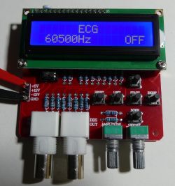
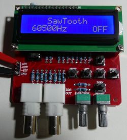
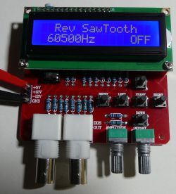
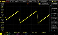
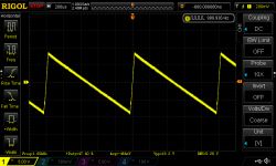
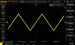
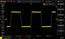
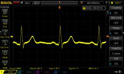
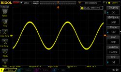
    1KHz waveform appearance sine, saw, inverted saw, triangle, rectangle, ECG:
    DDS function generator set for assembly, commissioning and tests DDS function generator set for assembly, commissioning and tests DDS function generator set for assembly, commissioning and tests DDS function generator set for assembly, commissioning and tests DDS function generator set for assembly, commissioning and tests DDS function generator set for assembly, commissioning and tests

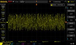
    "Noise":
    DDS function generator set for assembly, commissioning and tests DDS function generator set for assembly, commissioning and tests

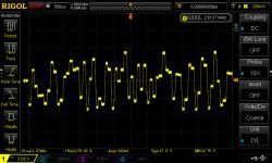
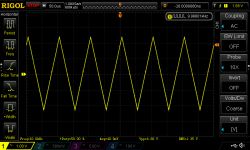
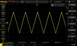
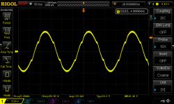
    5KHz sine and triangle, you can see the distortion:
    DDS function generator set for assembly, commissioning and tests DDS function generator set for assembly, commissioning and tests

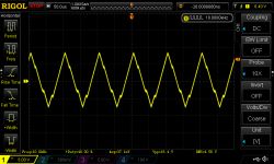
    10KHz sine and triangle, the sine is like a triangle:
    DDS function generator set for assembly, commissioning and tests DDS function generator set for assembly, commissioning and tests

    10KHz sine and delta at DAC output, better output amplifier can improve the parameters:
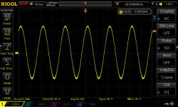
    DDS function generator set for assembly, commissioning and tests DDS function generator set for assembly, commissioning and tests

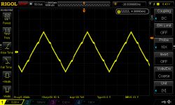
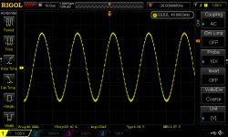
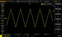
    40KHz sine and triangle at the amplifier output and the DAC output:
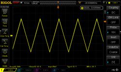
    DDS function generator set for assembly, commissioning and tests DDS function generator set for assembly, commissioning and tests
    DDS function generator set for assembly, commissioning and tests DDS function generator set for assembly, commissioning and tests

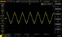
    Sine and triangle 65KHz at the output of the amplifier, apart from distortions, you can see changes in amplitude:
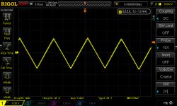
    DDS function generator set for assembly, commissioning and tests DDS function generator set for assembly, commissioning and tests

    65KHz sine and triangle at the DAC output:
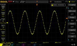
    DDS function generator set for assembly, commissioning and tests DDS function generator set for assembly, commissioning and tests

    Do you see an application for this DDS generator, e.g. in audio applications, is it worth modifying the output amplifier circuit?

    Replacing the operational amplifier and improving the parameters of the DDS generator: https://www.elektroda.pl/rtvforum/topic3445820.html

    Cool? Ranking DIY
    About Author
    TechEkspert
    Editor
    Offline 
    TechEkspert wrote 4929 posts with rating 4029, helped 12 times. Been with us since 2014 year.
  • #2
    leonow32
    Level 30  
    What is this processor? Maybe it would be worth considering a dedicated DDS chip like AD9851 etc. It is not that expensive, and the quality and possibilities are much greater.
  • #3
    paluszasty
    Level 25  
    No wonder it looks so faint. In my opinion, the lack of a normal DAC disqualifies this circuit. Look, the R-2R ladder uses resistors with a tolerance of 1%. From such resistors, a maximum of 6 bit converter can be made (64 levels). For the 8 bit converter (256 levels) 0.1% resistors must be used.
  • #4
    miszczo997
    Level 28  
    @ leonow32 prices for ad9850 have gone up terribly lately, I think stocks are running out. The ad9833, on the other hand, is cheap and allows you to directly generate various waveforms.
  • #6
    leonow32
    Level 30  
    miszczo997 wrote:
    @ leonow32 prices for ad9850 have gone up terribly lately, I think stocks are running out. The ad9833, on the other hand, is cheap and allows you to directly generate various waveforms.

    Indeed, the bastards have traveled several times over! But any DAC or a microcontroller with a built-in DAC could be used. The R-2R ladder is for breaking open the door.
  • #7
    paciek74
    Level 13  
    A few years ago it was made by electronics-lab, although I designed the plates from scratch to have a front panel. The system works, I have it, I use it.
  • #8
    kranzio
    Level 26  
    miszczo997 wrote:
    @ leonow32 prices for ad9850 have gone up terribly lately, I think stocks are running out. The ad9833, on the other hand, is cheap and allows you to directly generate various waveforms.

    The author of the post did not copy. This generator is available on aliexpress and that's where it comes from.
  • #9
    ArturAVS
    Moderator HP/Truck/Electric
    Overall useful device. Only this D / A converter on the ladder spoils everything.
    A D / A like DAC0832 would be a lot better.
  • #10
    TechEkspert
    Editor
    DAC or ladder with better resistors and perhaps a voltage source would give better results as well as a better amplifier circuit,
    the microcontroller used is an ATmega16 clocked with a 16MHz quartz.
  • #11
    Razorek01
    Level 9  
    Better performance amplifier and regenerative filter ...
  • #12
    Anonymous
    Anonymous  
  • #13
    Stefan_2000
    Level 19  
    Razorek01 wrote:
    Better performance amplifier and regenerative filter ...

    What is a regenerative filter?
  • #14
    Razorek01
    Level 9  
    Stefan_2000 wrote:
    What is a regenerative filter?

    A low-pass filter at the output of the D / A converter, whose task is to filter out the higher frequency components in the spectrum of the reproduced signal. The filter should have a steep slope to ensure adequate suppression of unwanted components with the largest possible bandwidth.
  • #15
    TechEkspert
    Editor
    I replaced the LM358 amplifier in the stand with TL082 (I also tested TL072),
    more information here: https://www.elektroda.pl/rtvforum/topic3445820.html

    For me, such a trivial upgrade gives very good results and increases the capabilities of this DDS generator.

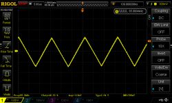
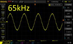
    This is a 65kHz sine wave on TL082:
    DDS function generator set for assembly, commissioning and tests

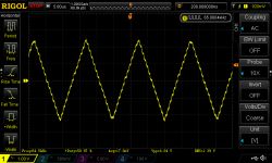
    and this is what the LM358 looked like ...
    DDS function generator set for assembly, commissioning and tests
  • #16
    leonow32
    Level 30  
    or maybe insert something more contemporary? Eg MCP6002 or MCP6022? 100% CMOS, rail is tail and 10MHz will pull, and costs about PLN 5
  • #17
    TechEkspert
    Editor
    Everything can be done, I had TL082 on the spot, the effect was very good and sufficient (looking at the capabilities of the tested DDS).
    For DDS with higher output frequencies, the MCP60XX series can be a good solution.
  • #18
    radiosimon
    Level 28  
    I noticed in the description that there is a 1Hz jump. What f is it used for? Up to 65kHz? I have the source of this software from 2008. but I can't quite get it out.
    I mean the possibility of using a similar system as a stepper motor speed adjuster.
  • #19
    TechEkspert
    Editor
    @radiosimon in the DDS mode in the range from 0-65535Hz, 1Hz, 10Hz, 100Hz, 1000Hz, 10000Hz steps are available.
    In HS mode, you can select the frequency of the square wave output as 1MHz, 2MHz, 4MHz, 8MHz.
    Any changes can be made with the signal generation turned off, i.e. we cannot smoothly tune the output frequency.

    I assume that the stepper motor driver requires a square wave signal, such a signal can be generated using, for example, NE555, or any microcontroller and built-in counter. No DDS is needed for a square wave signal, just an output that changes logic states. I suspect smooth frequency tuning is needed, the DDS cannot achieve this.
  • #20
    ArturAVS
    Moderator HP/Truck/Electric
    TechEkspert wrote:
    jumps are available


    I guess retuning steps.
  • #21
    radiosimon
    Level 28  
    NE555 + potentiometer is an analog technique and I need it digitally.
    When it comes to timers + CPU it's just that easy it's not (smooth). Unless there's a trick on the show. The author of the first version of the DDS writes about the division of the fundamental frequency by 2 ^ 24 which gives him great precision, although it is not entirely clear to me. Neither do I mean 1: 1 copying, but just understanding the subject.

    I used 24bit phase accumulator () which determines the signal resolution of frequency. The bigger frequency I am generating the smaller resolution I get.
    If you would use 18,432 Mhz crystal, then your:
    Resolution = fCPU / 2 ^ 24 = 18432000/150994944 = 0.1220703125
    Then you can generate frequencies:
    fOUT = Accumulator * Resolution;
    Accumulator value is updated according to your selected frequency, what means last byte of Accumulator addresses the value form lookup table.
    I don't know if I explained well, but you can see similar project here:
    Mini DDS

    https://scienceprog.com/avr-dds-signal-generator-v10/

    I will ask differently: is it possible to set any frequency in the range 0-60kHz? E.g. 12345Hz? (only rectangle with 50% fill)
  • #22
    TechEkspert
    Editor
    @radiosimon using the timer in the microcontroller it is possible to generate rectangular signals with 50% duty cycle and with tuned frequency, the frequency will be close to the assumed one, depending on the used clock signal and the degree of division.

    For example, we have a microcontroller with a 16MHz signal,
    we want a frequency of 60kHz to appear on a specific pin,
    that is, we change the logical state of the pin 120 thousand. times per second.
    The logic state of the pin can be changed at each timer overflow.
    We assume we have a 16 bit timer that can count up to 65535.

    16,000,000 / 120,000 is about 133 and with this number of counts we want it to overflow and change the value on the pin.
    As a result, on the pin we get 60150Hz, and for the value 134 -> 59701Hz, 135-> 59259Hz.

    e.g. for 10kHz -> 800 and 801 is 9987Hz.

    For lower frequencies, e.g. 1kHz, we have 16,000,000 / 2,000 -> 8,000
    for the values 8000-> 1000Hz, 8001-> 999.7Hz

    So for lower output frequencies, as you write, we get a higher resolution.

    This is roughly how it works.

    In Excel, for example, you can easily simulate the deviation as a function of frequency.
  • #23
    radiosimon
    Level 28  
    TechEkspert wrote:
    e.g. for 10kHz -> 800 and 801 is 9987Hz.

    Well, ok, that is exactly every 1Hz (linear) in the entire "band" of 60kHz is it impossible or I am wrong? Anyway, even every 10Hz is the same problem (timer limitations).
    Let's take another example: I am looking for some resonant frequency and with this generator it may not be possible (omitting that the software does not allow to change f "on the fly").

    I use AD9833 + AVR for this but it's expensive and I'm looking for something simpler all the time. Maybe some suggestions?
  • #24
    Urgon
    Level 38  
    AVE ...

    Is AD9833 expensive? I don't know, I bought a module for less than PLN 12 with free shipping from China. The only problem may be the quality of the original quartz resonator, but having access to a better quality frequency meter, it could probably be calibrated using the firmware ...

    I also recommend having a look at this page about Bresenham's algorithm ...
  • #25
    TechEkspert
    Editor
    For frequency tuning ADXXXX or an analog generator will be OK. The solutions based on the timer in the microcontroller will regulate the period of the low / high signal with a resolution of one timer tick.

    Bresenham's algorithm it's something new for me, it looks interesting, I have to load.
  • #26
    Slawek K.
    Level 35  
    radiosimon wrote:
    TechEkspert wrote:
    e.g. for 10kHz -> 800 and 801 is 9987Hz.

    Well, ok, that is exactly every 1Hz (linear) in the entire "band" of 60kHz is it impossible or I am wrong? Anyway, even every 10Hz is the same problem (timer limitations).
    Let's take another example: I am looking for some resonant frequency and with this generator it may not be possible (omitting that the software does not allow to change f "on the fly").

    I use AD9833 + AVR for this but it's expensive and I'm looking for something simpler all the time. Maybe some suggestions?

    Expensive ? https://www.aliexpress.com/wholesale?catId=0&initiative_id=SB_20180325101542&SearchText=ad9833

    Greetings
  • #27
    excray
    Level 40  
    AD9833 cannot be used as a function generator. It can generate at most a sine or a triangle with a given frequency. But we cannot program our own course.
  • #28
    Urgon
    Level 38  
    AVE ...

    Most don't need their own waveform anyway for typical generator jobs. In a situation where you need arbitrary waveforms, you are probably already working on something expensive and complicated, so you can afford to buy an arbitrary waveform generator ...
  • #29
    Artur k.
    Admin of Audio group
    paluszasty wrote:
    No wonder it looks so faint. In my opinion, the lack of a normal DAC disqualifies this circuit. Look, the R-2R ladder uses resistors with a tolerance of 1%. From such resistors, a maximum of 6 bit converter can be made (64 levels). For the 8 bit converter (256 levels) 0.1% resistors must be used.

    The resolution of the converter is determined by the size of the input word, not the tolerance of the resistors.
    In this case, the input word has 8 bits and the tolerance of the resistors will not change this in any way.
    The converter's conversion accuracy depends on the tolerance of the resistors, and this applies to both a 6-bit and 8-bit converter. Why in 6 bit you don't want to give 0.1%? I do not understand why in a 6-bit converter you agree to a lower processing accuracy, and in 8-bit it bothers you.

    However, in this generator it does not make sense to use better than 1% resistors, because the resolution is only 20mV, which results from the size of the input word and the tolerance of the resistors will not change that. There will always be steps on the waveform even if we put 0.01% resistors.
  • #30
    jarek_lnx
    Level 43  
    Artur k. wrote:
    The resolution of the converter is determined by the size of the input word, not the tolerance of the resistors.
    In this case, the input word has 8 bits and the tolerance of the resistors will not change this in any way.
    It is assumed necessary that the (differential) transducer nonlinearity errors are at least of such a level that the transducer is monotonic. In other words, the error when changing by one bit should be smaller than the voltage change that should correspond to that one bit.

    It is quite reasonable to assume that for increasing numbers on the input, the output voltage can also only increase, the errors of the resistor values (and the output resistance uC) may cause that this condition is not met. It will be most noticeable when changing from 01111111 to 10000000, changing the oldest bit must give a higher voltage than the low seven bits and this requires a certain accuracy. If the resistance of the resistor at the MSB together with the resistance of the uC port has a 1% error, it will be more than 1LSB

    Therefore, connecting 16 uC outputs to the R-2R ladder will not give us a 16-bit converter, in the sense that the word will be 16-bit, but the useful number of bits, allowing to predictively influence the output voltage, will be significantly smaller.