Today we are flashing Tasmota to the Appio/Lumenix 9605 light switch, which is distinguished by the fact that the TYWE3S has non-standard GPIO pins inside. The switch discussed here works without a neutral wire and also offers control via RF 433MHz, which makes it a quite universal and future-proof choice, so I think it will be worth freeing it from the cloud.
A friend bought a set of switches and I installed Tasmota on them. There were different versions: single, double, triple, here I will present the double version. The price was about PLN 75 per piece, quite expensive, but some people prefer to buy in our country rather than try to get it cheaper from abroad. Interestingly, in the store the product was named as Lumenix 9605 , not Appio:
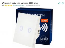
The seller truthfully points out that it is also possible to control this switch with an RF remote control:

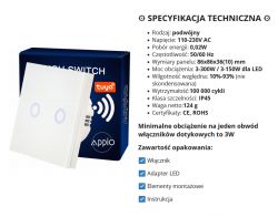
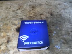
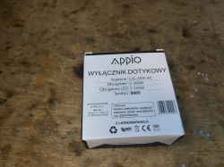
Appio box:
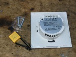
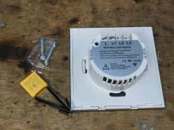
Set contents:
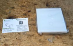
Instruction:

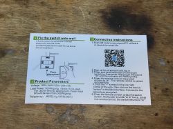


I do not discuss the control of the switch by the original application, the RF remote control and its connection. This was discussed earlier and is also included in the manual.
Appio 9605 interior
As standard, we remove the undermined front:
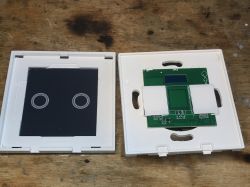
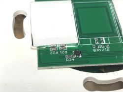
On its other side we can see the WiFi module and buzzer. This WiFi module seems to be an ordinary TYWE3S with ESP8266 inside, but it has different pins. More on that later.
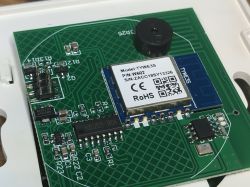
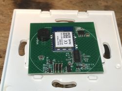
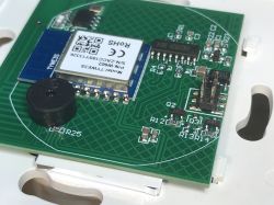
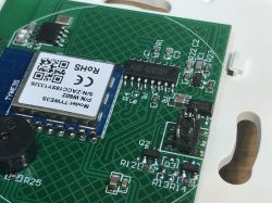
The buzzer and the system in SO8 with an additional antenna are from the RF 433MHz remote control receiver circuit. The larger HXD2029 chip is both for touch buttons and RF. The RF receiver is connected to it, which means that the WiFi module "does not know" that it is controlled by RF at all, so HXD2029 puts states 0 or 1 on individual pins that are connected to the GPIO of the WiFi module and in this way the WiFi module receives key presses.
There is also AMS1117-3.3V on the PCB, as usual, because the "power supply" board provides 5V and the WiFi module requires 3.3V.
To change the firmware, all we need to do is remove the board discussed above, but out of curiosity, you can also see the module with the power supply and relays:
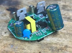
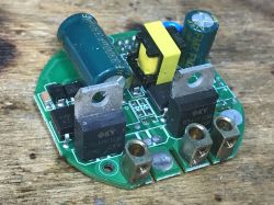
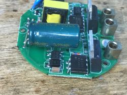
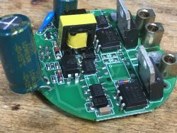
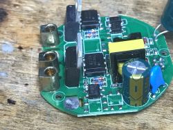
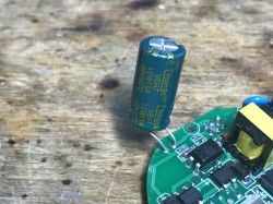
The bulb switching circuit is based on the GS10F10B triac controlled by MOC3063.
I have not analyzed here how this switch without the N wire works. I once drew a diagram of a similar switch in the topic QTouch WiFi switch plugged into the L cable only - test, interior, diagram but there was no time for that here.
Programming Tasmota Appio 9605
There was a problem with uploading Tasmota. It turned out that the TYWE3S module here has non-standard pinouts. RX, TX and GPIO0 are in different places than specified in the Tuya documentation. I posted the details in a separate topic:
Alternative/new GPIO pinout of TYWE3S/ESP8285 WiFi module, Tasmota
Tasmota Appio 9605 template
This time I was lucky. The template from a Github user matched. I am quoting the information I found in this topic : :
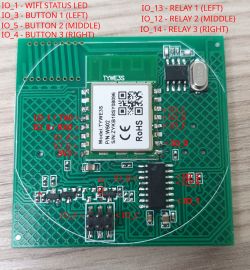
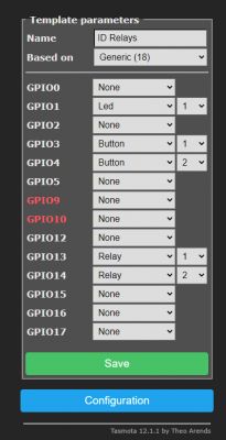
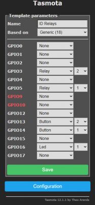
The first template has started working for me. Everything works:
If you want the switch to respond faster, it is worth turning on SetOption13 in Tasmota.
Summary
At first glance, it's a bit expensive, but there is both RF and it works in no-neutral mode...
Flashing is a bit worse. I lost some time before I realized that this TYWE3S has a non-standard pinout, but fortunately after that it went smoothly. Github also helped a bit, that's where I got the GPIO configuration.
It's also a pity that this switch does not have a programming connector (pads) and you have to solder it to the WiFi module itself, but you can still survive this.
If you are looking for something that is not based on one of the newer WiFi modules used by Tuya (BK7231T/BK7231N), you can try to use the switch from the topic.
I also have the 1-gang version in the queue and if necessary, I will also verify its configuration and post it.
Cool? Ranking DIY Helpful post? Buy me a coffee.


