Basic information:
Brand: KingArt
Chip: BK7231N
Local Vendor: https://shopee.com.my/Tuya-Ewelink-APP-1-2-3-...ort-Alexa-Google-Home-i.288391115.16846568433
Default option is touch button, but the seller informed me I could just request for a push button type.
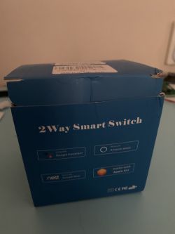
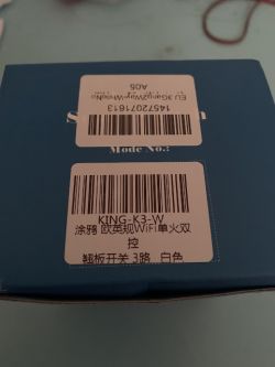
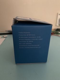
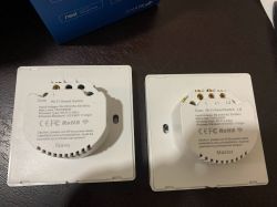
Teardown Photos:
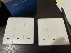
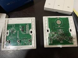
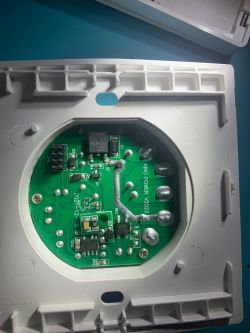
Tuya firmware dump:
Flashing:
Using serial method.
Wasn't sure which pad is the gnd so I just connect the 2nd female dupont connector on the back
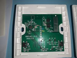
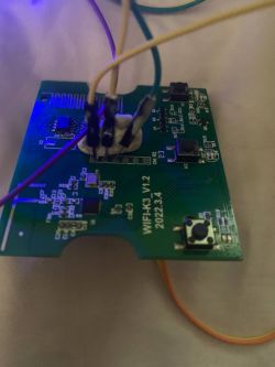
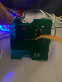
Pinout:
Json code:
Usage:
The slave switch buttons toggles the relay on the master but the leds stays the same (blue color), red led does briefly light when the button is pressed.
Since this one has dedicated pins for LED, it can be useful for detached mode.
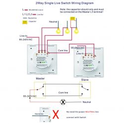
Capacitor needs to be on L3 on the light fixture for the switch to boot up.
Brand: KingArt
Chip: BK7231N
Local Vendor: https://shopee.com.my/Tuya-Ewelink-APP-1-2-3-...ort-Alexa-Google-Home-i.288391115.16846568433
Default option is touch button, but the seller informed me I could just request for a push button type.
Teardown Photos:


Tuya firmware dump:
Flashing:
Using serial method.
Wasn't sure which pad is the gnd so I just connect the 2nd female dupont connector on the back


Pinout:
- Button (channel 1) on P6
- Relay (channel 3) on P17
- LED (channel 1) on P8
- Button (channel 3) on P16
- LED (channel 3) on P26
- Relay (channel 2) on P14
- Button (channel 2) on P9
- LED (channel 2) on P15
- Relay (channel 1) on P7
Json code:
{
	"rl1_lv":"1",
	"bt_type":"1",
	"bt1_pin":"6",
	"rl3_pin":"17",
	"rl3_lv":"1",
	"led1_pin":"8",
	"rand_dpid":"18",
	"net_trig":"4",
	"cd_flag2":"1",
	"led_dp":"15",
	"jv":"1.0.0",
	"backlit_select":"1",
	"led2_lv":"1",
	"backlit_io_lv":"1",
	"backlit_io_pin":"28",
	"total_stat":"2",
	"bt3_lv":"0",
	"bt1_lv":"0",
	"reset_t":"6",
	"rl2_lv":"1",
	"ch_flag1":"1",
	"ch_flag3":"1",
	"inch_dp":"19",
	"module":"CBU",
	"bt3_pin":"16",
	"ch_cddpid1":"7",
	"led3_pin":"26",
	"init_conf":"14",
	"led1_lv":"1",
	"rl2_pin":"14",
	"light_status_select":"1",
	"bt2_pin":"9",
	"led3_lv":"1",
	"ch_cddpid2":"8",
	"ch_cddpid3":"9",
	"backlit_dp":"16",
	"cyc_dpid":"17",
	"ch_num":"3",
	"led2_pin":"15",
	"bt2_lv":"0",
	"rl1_pin":"7",
	"ch_dpid3":"3",
	"ch_dpid1":"1",
	"ch_dpid2":"2",
	"crc":"123",
	"}11Alight_mode_en1B)Asave_off_stat{power":"[false"
}
Usage:
The slave switch buttons toggles the relay on the master but the leds stays the same (blue color), red led does briefly light when the button is pressed.
Since this one has dedicated pins for LED, it can be useful for detached mode.
Capacitor needs to be on L3 on the light fixture for the switch to boot up.


