

Purchased from https://pl.aliexpress.com/item/1005005070248246.html
Unfortunately I don't have too many photos of the teardown itself, but rather nothing of interest.
Power is supplied via a 'bracket' which we screw onto the ceiling and plug it into 230V. When putting the lamp on the bracket, we put it on the bracket and rotate it until the 'spring' pins make contact. The L of 230V can easily be touched with a finger
The lamp itself has 2 flaps on the back - one secured with clips in the middle, under which the 230V cables hide, under the other secured with 2 short screws is the PCB with the CBU module.

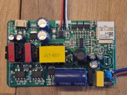
The LEDs are powered by 5V via 2 BP2958 drivers.
The CBU is wired to 5 pins - 8, 10, 11, 13, 14. It was supplied with a new software version, incompatible with the Tuya-Cutter. According to the specification 8-12 is PWM, it's not clear to me what the third PWM PIN is for, as the output only has two channels. In the middle is something labelled "U1", I am unable to catch what this component is.
Unfortunately, this is where my teardown ends - I am unable to sflash the device. I'm using BusPirate 3.6, I'm correctly splicing MISO/MOSI with TX/RX (I've tested both variants), GND, 3.3V is supplied by an external lab power supply. Programming does not go through the "Failed to get bus!" part. I tested all 3 baud rate presets.
CBU only had the bottom pins soldered, so I rule out the presence of any MCU interfering with TX/RX. I also previously tested the RP2040 in UART bridge mode, but this again did not like the flasher downloaded from Elektroda. The UART is silent, I can't see any data.
Have any ideas on how to bite this topic?
.
