logo elektroda
logo elektroda
X
logo elektroda

EXTRASTAR B22 A60BWIFI2 (RGBCW Lamp) - Transition from Tasmota Compatible MCU to BK7231N (CB2L)

sirhcsat 930 8
ADVERTISEMENT
  • #1 20780465
    sirhcsat
    Level 7  
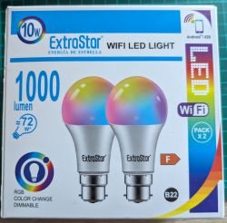
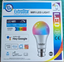
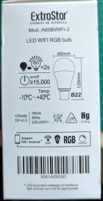
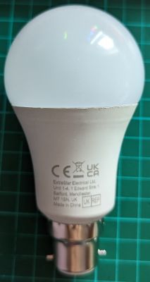
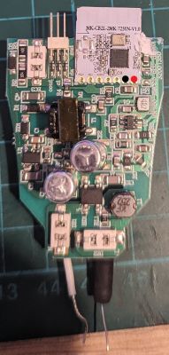
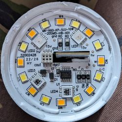
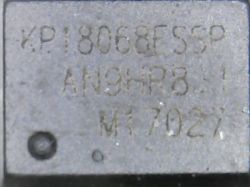
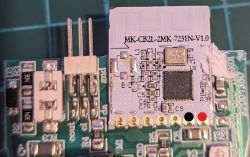
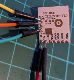
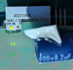
    Package of ExtraStar B22 WiFi LED bulbs. ExtraStar B22 WiFi LED 10W bulb packaging. Box of EXTRASTAR LED bulb A60BWIFI-2 displaying technical specifications. Smart bulb EXTRASTAR B22 A60BWIFI-2 with visible CE and UKCA markings. Printed circuit board with MK-CB2L-2MK-7231N-V1.0 electronic module. Printed circuit board with visible LED components. Close-up of a microchip with markings KP18068ESSP AN9HR81 M17027. MK7231N module labeled as MK-CB2L-2 on a circuit board. MK-CB2L_7231N-V1.0 module connected with jumper wires. Close-up of MK-CB2L-7231N-V1.0 module with TX and RX labels.


    I bought from ebay what was supposed to be EXTRASTAR B22 A60BWIFI Lamps.
    What arrived was a different version (EXTRASTAR B22 A60BWIFI-2) and that has been updated to remove a good tasmota compatable mcu with a replaced with BK7231N (CB2L)

    With a little bit of prodding, poking & hair tearing I have it flashed now and mostly working with Alexa ( needs more work to make it work as it should. )


    2mb original flash is available if anyone wants it but I tried to flash the device back to original and nothing worked so I must have messed it up, poss by just dumping and flashing before it was ever plugged in and used/setup.

    Dump from original firmware .json format :-

    Code: JSON
    Log in, to see the code


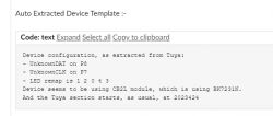
    Auto Extracted Device Template :-

    Device configuration, as extracted from Tuya: 
    - UnknownDAT on P8
    - UnknownCLK on P7
    - LED remap is 1 2 0 4 3
    Device seems to be using CB2L module, which is using BK7231N.
    And the Tuya section starts, as usual, at 2023424


    Decrypted from Original firmware

    Code: JSON
    Log in, to see the code


    After a lot of reading etc this is what I come up with and seems to work but Cool & warm white are reversed from http page.

    Code: JSON
    Log in, to see the code


    The device is found as a switch and can be changed in alexa to a light but that is about as far as it goes.
    From reading there is still background work to be done by the devs and more informed people than me on how to make this work better, getting alexa to change colour with hue etc but it`s a start for another lamp type.
  • ADVERTISEMENT
  • #2 20780531
    p.kaczmarek2
    Moderator Smart Home
    Whoa, it looks like a sample JSON for KP18058! This is very helpful. Thanks to this we will be able to make our automatic template configuration system even better! I've been looking for that kind of data sample for a very long time.

    Added after 4 [minutes]:

    EDIT: I have, however, one question about your config.

    Why do you have PWM pins set, if this is KP18058 (or KP18068, to be exact) device?
    Helpful post? Buy me a coffee.
  • ADVERTISEMENT
  • #3 20780713
    sirhcsat
    Level 7  

    It is a KP18068, I think I took a picture of the chip..

    As for the PWM. I have no idea what I was doing while I was tinkering with it. I just thought since it had 5 pins out that 2 were used for clock and data and the other 3 are for cold white, warm white, and the RGB LED. I have only had about 2 hrs of tinkering spread over a week and I am still learning about this setup as most of my other devices are Tasmota compatible.

    Any help you could offer would be great. If my assumptions are wrong, please feel free to correct them and I can continue to tinker.

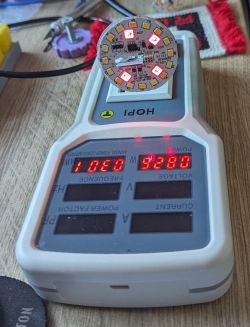
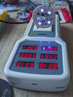
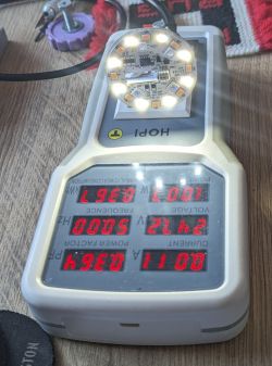
    One problem I have found is that the board and LEDs work great on the test bench, but when I put the lamp back together, the Wi-Fi is very weak and drops out.

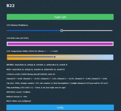
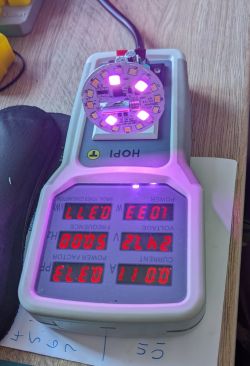
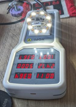
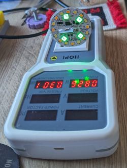
    A few images with low intensity light.
    LED lighting control interface with sliders for brightness, RGB color, and temperature adjustment. LED board placed on a voltage meter. Illuminated LED circuit board on a measuring device. LED board with green diodes on a power meter. Photo of a round LED circuit board placed on an electrical meter. LED light circuit placed on an energy consumption meter. LED board on a HOPI measurement device.
  • #4 20781052
    p.kaczmarek2
    Moderator Smart Home
    Well, those I2C-like LED drivers are always using two lines for communication, but they control all channels. So I would suggest to remove PWM pins, set them back to None, and then recheck if everything is still working.

    Regarding WiFi range issue - by any chance, is your device's MAC ending with 00? That could indicate lost RF data.

    Apart from that, it should work correctly... you may try to use PowerSave 1 to reduce power usage, but it should not affect that.

    PS: With OBK, this bulb is mostly Tasmota compatible, for example, Tasmota device groups will work:
    https://www.youtube.com/watch?v=e1xcq3OUR5M&ab_channel=Elektrodacom
    Helpful post? Buy me a coffee.
  • #5 20781347
    sirhcsat
    Level 7  
    After a little light reading on the forum, I found some info about the i2c control. Then, I removed the pwm settings and references, and the lamp still works as is.
    What confused me was the decrypted pin lines about 5 pwm channels found, so I just took it the controller was using 3 pwm for the dimming of relevant LEDs.

    Code: JSON
    Log in, to see the code


    Not to worry, I will look into the wifi when I get a chance. I will edit the top post to remove those pwm references so it does not mislead any others reading the thread. ?
  • ADVERTISEMENT
  • #6 20781899
    p.kaczmarek2
    Moderator Smart Home
    Where did you get message about 5 PWMs?

    In the first post I can see:
    Photo of extracted device template with code and configuration related to a Tuya driver.
    It indicates that my tool has detected an I2C-like LED controller using (as I2C does) two lines, SDA and SCL. It has also futhermore detected the RGBCW colors remap order for that driver, because the order of channels is not standarized and may vary between devices.
    Helpful post? Buy me a coffee.
  • ADVERTISEMENT
  • #7 20781935
    sirhcsat
    Level 7  

    The PWM info comes from the initial page after launching the web application. In the "Export Current Template" block, when I started to configure the settings, I do not know if it defaulted to those settings once I had found the network IP address and logged into the lamp.
  • #8 20781978
    p.kaczmarek2
    Moderator Smart Home
    I must admit that I am suprised. I do not know anything about "initial PWM config". Maybe you have just tried to select a bulb within Web App from the devices list there and somehow imported those PWMs?
    Helpful post? Buy me a coffee.
  • #9 20782128
    sirhcsat
    Level 7  

    I possibly did that while trying to work out what was what. Looks like it was a fault on my behalf as I just extracted the config from the original backup and it only shows the unknown clk & dat pins.

    Device configuration, as extracted from Tuya:
    - Unknown DAT on P8
    - Unknown CLK on P7
    - LED remap is 1 2 0 4 3
    Device seems to be using CB2L module, which is using BK7231N.
    And the Tuya section starts, as usual, at 2023424

    My error trying to run before I could walk. Thanks

Topic summary

The discussion revolves around the EXTRASTAR B22 A60BWIFI-2 lamp, which was purchased as a Tasmota-compatible device but instead features a BK7231N (CB2L) MCU. The user successfully flashed the lamp after some troubleshooting. Participants discuss the configuration of the device, particularly the PWM settings and I2C communication for LED control. Issues with Wi-Fi connectivity were noted, particularly when the lamp was reassembled, leading to suggestions for troubleshooting and configuration adjustments. The conversation highlights the importance of understanding the device's architecture and the correct settings for optimal performance.
Summary generated by the language model.
ADVERTISEMENT