logo elektroda
logo elektroda
X
logo elektroda

[Solved] Configuring OBK-Flashed RGB LED Corner Lamp KB-1500B with BK7231N CBU from Aliexpress

bruceda 4044 23
ADVERTISEMENT
  • #1 20515385
    bruceda
    Level 3  
    Hi everyone

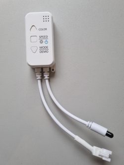
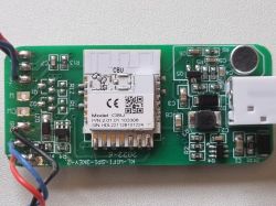
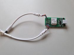
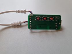
    I have an RGB LED corner lamp that I have flashed with OBK, using Tuya CloudCutter. The lamp is from AliExpress, model KB-1500B. The module is a BK7231N CBU. It includes WiFi, Bluetooth, IR remote and a microphone to sync lights to music. I have traced the buttons and can see the button presses in the web app logs.

    Any tips to find the rest of the config I need?

    Configuring OBK-Flashed RGB LED Corner Lamp KB-1500B with BK7231N CBU from Aliexpress Configuring OBK-Flashed RGB LED Corner Lamp KB-1500B with BK7231N CBU from Aliexpress Configuring OBK-Flashed RGB LED Corner Lamp KB-1500B with BK7231N CBU from Aliexpress Configuring OBK-Flashed RGB LED Corner Lamp KB-1500B with BK7231N CBU from Aliexpress Configuring OBK-Flashed RGB LED Corner Lamp KB-1500B with BK7231N CBU from Aliexpress Configuring OBK-Flashed RGB LED Corner Lamp KB-1500B with BK7231N CBU from Aliexpress
  • ADVERTISEMENT
  • Helpful post
    #2 20515416
    p.kaczmarek2
    Moderator Smart Home
    Hello @bruceda ,
    do you have original binary file? We could extract GPIO roles from there.

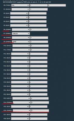
    If not, please note that BK7231N has six possible PWM pins. You can see that even in our configuration page:
    Configuring OBK-Flashed RGB LED Corner Lamp KB-1500B with BK7231N CBU from Aliexpress
    So, you are looking for 3 PWMs for RGBs and you have 6 possible PWM pins.
    There is not much to test.
    So I'd suggest it: For all 6 PWMs, set a Relay role, set channel 0 for PWM0, channel 1 for PWM 1, etc.
    Then try toggling each relay (while remembering on which PWM pin is it) and note which LED strip color changes.
    That way you can quickly narrow down to the 3 PWM pins you are looking for.

    Once you have already figured out correctly 3 PWM pins, then change their roles to PWM, as they should be, and then setup their channel order so Red is Red, Green is Green, etc... Remember, channel 0 is Red, 1 is green, 2 is blue. It will also work if you start numbering from 1.

    TLDR: guessing 3 PWMs from 6 possible PWMs is quick and easy to do.

    Alternate option would be to open CBU pinout on Tuya page, see which pins are PWMs are probe them with multimeter to see which PWMs are connected to MOSFETs


    EDIT:
    Sorry, I reviewed the images again, and it seems you don't have a PWM-based device. What is the marking on the chip on the LED strip?
    Helpful post? Buy me a coffee.
  • #3 20518768
    bruceda
    Level 3  
    Sorry, slow reply

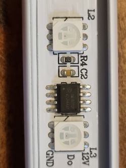
    The chip on the LED strip says SM16703P and KZBSAFAC21

    I don't have the original binary from the device, I stupidly rushed into flashing it in my enthusiasm to try out your work.
  • ADVERTISEMENT
  • #4 20520009
    p.kaczmarek2
    Moderator Smart Home
    SM16703P has been reported so far on only one device from Action store and driver is WIP but we have a slight issue with flash caching. We can give it another try for you, but unfortunately right now this particular chip is not yet supported.

    Those chips are very, very rare. We usually have PWM-based devices or with "i2c-like" LED drivers. Tens of thems.

    Would you like to help us with testing the future driver? Or do you have some knowledge and can help with implementation?
    Helpful post? Buy me a coffee.
  • ADVERTISEMENT
  • #5 20520070
    bruceda
    Level 3  
    Hi

    Happy to help with both the testing and driver development. I'm not experienced with this sort of thing but I have a background in technology, including development and electronics. Don't worry, I'm not someone's nanna asking for help with getting on the line to use the interwebs :-)
  • #6 20709852
    p.kaczmarek2
    Moderator Smart Home
    @bruceda can you try?

    To test this you can follow these steps:

    1. Start driver
    startDriver SM16703P


    2. Init Driver
    SM16703P_Init [[pixelcount]]


    3. Set Pixel
    SM16703P_SetPixel 1 255 0 0
    SM16703P_SetPixel 2 0 255 0
    SM16703P_SetPixel 3 0 0 255


    4. Start Output (each call will trigger one
    SM16703P_Start
    Helpful post? Buy me a coffee.
  • #7 20725135
    bruceda
    Level 3  
    @p.kaczmarek2
    Apologies for the slow reply, I just saw your message now. Thank you for suggesting the above commands.

    I have tried applying them and I have included the logged output below. I enabled ExtraDebug to give as much detail as possible. I left MAIN and GEN disabled to cut down on logging noise.

    Debug:API:POST to api/cmnd
    Debug:CMD:cmd [startDriver SM16703P]
    Debug:CMD:Adding command SM16703P_Init
    Debug:CMD:Adding command SM16703P_Start
    Debug:CMD:Adding command SM16703P_SetPixel
    Info:CMD:[WebApp Cmd 'startDriver SM16703P' Result] OK
    Debug:API:POST to api/cmnd
    Debug:CMD:cmd [SM16703P_Init 90]
    Info:CMD:Register driver with 90 LEDs
    Debug:CMD:spi master dma init: mode:0, rate:3000000
    Debug:CMD:max_hz = 3000000
    Debug:CMD:spi_master:[CTRL]:0x00c20400
    Debug:CMD:spi_master [CTRL]:0x00c20400
    Debug:CMD:spi_master [CONFIG]:0x0000000c
    Debug:CMD:spi dma tx init
    Debug:CMD:spi dma tx config: length:1082, first:0
    Info:CMD:[WebApp Cmd 'SM16703P_Init 90' Result] OK
    Debug:API:POST to api/cmnd
    Debug:CMD:cmd [SM16703P_SetPixel 1 255 0 0]
    Info:CMD:Set Pixel 1 to R 255 G 0 B 0
    Info:CMD:Raw Data 0xee 0xee 0xee 0xee - 0x88 0x88 0x88 0x88 - 0x88 0x88 0x88 0x88
    Info:CMD:[WebApp Cmd 'SM16703P_SetPixel 1 255 0 0' Result] OK
    Debug:API:POST to api/cmnd
    Debug:CMD:cmd [SM16703P_SetPixel 2 0 255 0]
    Info:CMD:Set Pixel 2 to R 0 G 255 B 0
    Info:CMD:Raw Data 0x88 0x88 0x88 0x88 - 0xee 0xee 0xee 0xee - 0x88 0x88 0x88 0x88
    Info:CMD:[WebApp Cmd 'SM16703P_SetPixel 2 0 255 0' Result] OK
    Debug:API:POST to api/cmnd
    Debug:CMD:cmd [SM16703P_SetPixel 3 0 0 255]
    Info:CMD:Set Pixel 3 to R 0 G 0 B 255
    Info:CMD:Raw Data 0x88 0x88 0x88 0x88 - 0x88 0x88 0x88 0x88 - 0xee 0xee 0xee 0xee
    Info:CMD:[WebApp Cmd 'SM16703P_SetPixel 3 0 0 255' Result] OK
    Debug:API:POST to api/cmnd
    Debug:CMD:cmd [SM16703P_Start]
    Error:CMD:before enable tx 0x00043a0c
    Error:CMD:enable tx 0x00043a0d
    Debug:CMD:spi dma tx finish callback
    Info:CMD:[WebApp Cmd 'SM16703P_Start' Result] OK

    When I power on the controller all LEDs go bright white. When I execute the SM16703P_Start command the bottom 3 LEDs stay white, the next 3 are blue, next 3 red and then 3 green. After that the remaining LEDs all stay bright white. I can't get a good photo of this, the camera won't pick up the colours.
  • #8 20725246
    p.kaczmarek2
    Moderator Smart Home
    What if you do:
    
    SM16703P_SetPixel 1 255 0 0
    SM16703P_SetPixel 2 0 255 0
    SM16703P_SetPixel 3 0 0 255
    SM16703P_SetPixel 4 255 0 0
    
    Helpful post? Buy me a coffee.
  • #9 20726415
    bruceda
    Level 3  

    I get a similar result but now there are three extra blue LEDs at the top of the colored sequence with the rest still bright white.
    Here is the output:
    Debug:API:POST to api/cmnd
    Debug:CMD:cmd [startDriver SM16703P]
    Debug:CMD:Adding command SM16703P_Init
    Debug:CMD:Adding command SM16703P_Start
    Debug:CMD:Adding command SM16703P_SetPixel
    Info:CMD:[WebApp Cmd 'startDriver SM16703P' Result] OK
    Debug:API:POST to api/cmnd
    Debug:CMD:cmd [SM16703P_Init 90]
    Info:CMD:Register driver with 90 LEDs
    Debug:CMD:spi master dma init: mode:0, rate:3000000
    Debug:CMD:max_hz = 3000000 
    Debug:CMD:spi_master:[CTRL]:0x00c20400 
    Debug:CMD:spi_master [CTRL]:0x00c20400 
    Debug:CMD:spi_master [CONFIG]:0x0000000c 
    Debug:CMD:spi dma tx init
    Debug:CMD:spi dma tx config: length:1082, first:0
    Info:CMD:[WebApp Cmd 'SM16703P_Init 90' Result] OK
    Debug:API:POST to api/cmnd
    Debug:CMD:cmd [SM16703P_SetPixel 1 255 0 0]
    Info:CMD:Set Pixel 1 to R 255 G 0 B 0
    Info:CMD:Raw Data 0xee 0xee 0xee 0xee - 0x88 0x88 0x88 0x88 - 0x88 0x88 0x88 0x88
    Info:CMD:[WebApp Cmd 'SM16703P_SetPixel 1 255 0 0' Result] OK
    Debug:API:POST to api/cmnd
    Debug:CMD:cmd [SM16703P_SetPixel 2 0 255 0]
    Info:CMD:Set Pixel 2 to R 0 G 255 B 0
    Info:CMD:Raw Data 0x88 0x88 0x88 0x88 - 0xee 0xee 0xee 0xee - 0x88 0x88 0x88 0x88
    Info:CMD:[WebApp Cmd 'SM16703P_SetPixel 2 0 255 0' Result] OK
    Debug:API:POST to api/cmnd
    Debug:CMD:cmd [SM16703P_SetPixel 3 0 0 255]
    Info:CMD:Set Pixel 3 to R 0 G 0 B 255
    Info:CMD:Raw Data 0x88 0x88 0x88 0x88 - 0x88 0x88 0x88 0x88 - 0xee 0xee 0xee 0xee
    Info:CMD:[WebApp Cmd 'SM16703P_SetPixel 3 0 0 255' Result] OK
    Debug:API:POST to api/cmnd
    Debug:CMD:cmd [SM16703P_SetPixel 4 255 0 0]
    Info:CMD:Set Pixel 4 to R 255 G 0 B 0
    Info:CMD:Raw Data 0xee 0xee 0xee 0xee - 0x88 0x88 0x88 0x88 - 0x88 0x88 0x88 0x88
    Info:CMD:[WebApp Cmd 'SM16703P_SetPixel 4 255 0 0' Result] OK
    Debug:API:POST to api/cmnd
    Debug:CMD:cmd [SM16703P_Start]
    Error:CMD:before enable tx 0x00043a0c
    Error:CMD:enable tx 0x00043a0d
    Debug:CMD:spi dma tx finish callback
    Info:CMD:[WebApp Cmd 'SM16703P_Start' Result] OK


    I tried adding:
    SM16703P_SetPixel 5 0 255 0
    SM16703P_SetPixel 6 0 0 255

    Doing this, the pattern just continues, 3W, 3B, 3R, 3G, 3B, 3R, 3G then all the rest are white
  • #10 20732999
    jkwim
    Level 12  
    Interesting discussion.

    SM16703P LED Strips work in a similar fashion to WS2811 LED Strips. That is, a data stream needs to be transmitted to the Din of the first LED and then transmitted out via the Dout connection in the LED. An arrow on the LED strip marks the direction of the data flow.

    Some LED strips are made with 3 LEDs being controlled by a single control chip. These work by changing color in 3 LEDs at once. From the description, the OP's device seems to have this kind of strip.

    I did not realize that OpenBK had a configuration option for SM16703 strips.

    In Tasmota, the command LEDx is used to set the colors of each LED in the strip. That is, if I need the first 3 LEDs to be Color1, Color2, and Color3, there are two ways to achieve it.

    1. Use Three commands:
    LED1 Color1
    LED2 Color2
    LED3 Color3

    2. A single command:
    LED Color1 Color2 Color3

    So can somebody explain what would be the corresponding commands on OpenBK to achieve a similar setup.

    Once that is known, each LED can be tested, and then a script can be formulated to light up the LEDs in any fashion.

    Also,

    Yes, Also (with a smile)

    using DDP, it should be possible to drive a LED animation by integrating with WLED. I have successfully integrated a couple of RGB Smart Bulbs with WLED to run an animation from WLED. So in the same manner, we should be able to integrate a Pixel LED strip using DDP protocol. Each LED can be addressed separately.

    I am trying to figure out which of my devices can be quickly hacked to add a LED strip.


    Added after 3 [hours] 41 [minutes]:

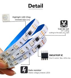
    Found these two images from the internet which suggest that there could be two variants of 16703 chips.

    One says that the chip controls 3 x LEDs the other one (which is SM16703P) controls 6 LEDs.

    If the OP can attach a photo with a longer part of the strip visible we could determine correctly which is what.


    1. MT16703
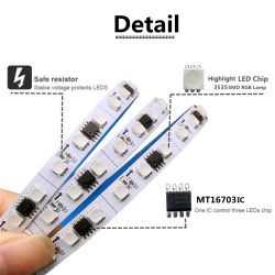
    Image of LED strips with visible MT16703IC and SM16703P chips, labeled Detail.

    2. SM16703P
    Close-up of an LED strip with SM16703P chip, capable of controlling six LEDs.
  • #11 20733874
    bruceda
    Level 3  

    Welcome to the conversation @jkwim.

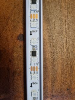
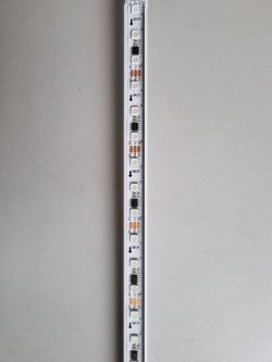
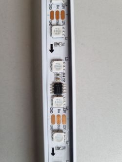
    Here are some additional images. My strip looks closer to the MT16703 image than the SM16703P image that you included. You can see in the second, closer image below that there is one chip per three LEDs. This also matches the behavior I observed when testing the commands noted above.

    Image of an LED strip with three LEDs per chip. Close-up of an LED strip with three LEDs per chip.
  • #12 20733941
    jkwim
    Level 12  
    Ok! Now things make sense.

    SM16703P_SetPixel 1 255 0 0
    SM16703P_SetPixel 2 0 255 0
    SM16703P_SetPixel 3 0 0 255
    SM16703P_SetPixel 4 255 0 0
    SM16703P_SetPixel 5 0 255 0
    SM16703P_SetPixel 6 0 0 255

    
                 3W, 3B, 3R, 3G, 3B, 3R, 3G
    LED segments 0   1   2   3   4   5   6


    So you got 6 segments covered.

    Add a command for LED Segment 0
    
    SM16703P_SetPixel 0 255 0 0


    That should turn the first segment into Blue.

    So depending on the number of segments in the strip, add additional SetPixel command and you could have all of them change color.

    However, there is a catch. Generally, the LED strips have a different color order.

    From the look of things, your strip has BRG instead of RGB.
    SM16703P_SetPixel 1 255 0 0
                         B  R G


    So by adopting the correct notation, you could now make them into any color that you want.

    The driver for SM16703 appears to be working.

    Now you need to see how fast it can change colors. Perhaps a loop which changes the color in some pattern will show how fast the colors can be changed. Then you can add a delay between each iteration to slow down the change to suit the eye.

    Added after 15 [minutes]:

    I think it is time that I grab a device where I can solder a wire to an unused PWM pin and try this driver with a WS2812 strip that I have. If it works I will be dancing.

    Thank you all for this discussion.
  • #13 20734037
    p.kaczmarek2
    Moderator Smart Home
    Ah, so there is one strip per 3 LEDs... and here I thought we have a bug!

    @jkwim , the following driver is using hardware SPI port, which Data Out pin is available only on P16. This is a limitation on Beken side.

    Added after 37 [minutes]:

    WS2812B test with OBK:


    Script:
    
    
    setChannel 10 1
    
    again:
    addChannel 10 1
    SM16703P_SetPixel $CH10-2 0 0 255
    SM16703P_SetPixel $CH10-1 0 255 0
    SM16703P_SetPixel $CH10 255 0 0
    SM16703P_Start
    delay_s 0.5
    goto again
    
    Helpful post? Buy me a coffee.
  • #14 20734889
    jkwim
    Level 12  

    Great!
    We have smoke now!

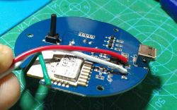
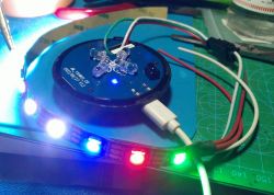
    I soldered a JST connector to P16 of CBU module of my IR Remote Controller and connected a WS2812 LED strip. The strip color order is GRB.
    Tapped 5V and GND from AMS1117 regulator input. That is USB +5V and GND theoretically so as long as the USB port receives enough current from an external power supply, the number of LEDs can be increased without compromising the capacity of the AMS1117.

    Close-up of a blue PCB with connected wires, a microcontroller, and a USB port.

    Close-up of an electronic module with a WS2812 LED strip connected to a connector, with LEDs shining in different colors.

    startDriver SM16703P
    SM16703P_Init 16
    SM16703P_SetPixel 0 255 0 0
    SM16703P_SetPixel 1 0 255 0
    SM16703P_SetPixel 2 0 0 255
    SM16703P_Start


    However, I got different observations when I tried your looping script.

    After initial progression, the colors changed in a different manner. I have a feeling that the color gets mixed with previous colors instead of refreshing.

    BTW, I need to understand the "Channels" better as it is not very clear what a Channel is in this context.
  • #15 20735456
    jkwim
    Level 12  

    Today I hit an issue.

    I changed the delay time to be 0.2 seconds.

    Now the device does not connect to WiFi anymore.

    I can get into AP Mode (by power on/off x5 times).

    How can I disable autoexec.bat using the command prompt in basic GUI? App launch is not possible in AP Mode.
  • ADVERTISEMENT
  • #16 20736178
    p.kaczmarek2
    Moderator Smart Home
    I think you should be still able to use lfs_format, at least after you do unsafe start.
    Helpful post? Buy me a coffee.
  • #17 20736429
    jkwim
    Level 12  
    p.kaczmarek2 wrote:
    I think you should still be able to use lfs_format, at least after you do an unsafe start.

    lfs-format
    worked!
    Screenshot of the Command Tool showing messages about formatting and mounting.
    Thank you


    Added after 5 [hours] 59 [minutes]:

    I am trying to build a script based on your example above for a simple animation.

    Your script did not have a over flow detection in the loop so I am trying the following:

    startDriver SM16703P
    SM16703P_Init 16
    //SM16703P_SetPixel 0 255 0 0
    //SM16703P_SetPixel 1 0 255 0
    //SM16703P_SetPixel 2 0 0 255
    //SM16703P_Start
    
    alias InitChannel10 setChannel 10 1
    //setChannel 10 1
    InitChannel10
    
    again:
    addChannel 10 1
    echo "1: $CH10"
    if $CH10>16 then InitChannel10
    echo "2: $CH10"
    //SM16703P_SetPixel $CH10-2 0 0 255
    //SM16703P_SetPixel $CH10-1 0 255 0
    //SM16703P_SetPixel $CH10 255 0 0
    //SM16703P_Start
    delay_s 0.5
    goto again


    Response:
    Info:GEN:CHANNEL_Add channel 10 has changed to 12507
    
    Info:GEN:CHANNEL_Set channel 10 has changed to 12507 (flags 0)
    
    Info:CMD:"1: 12507"
    Error:CMD:cmd InitChannel10 NOT found (args )
    Info:CMD:"2: 12507"


    I am having trouble getting the following working

    if $CH10>16 then InitChannel10


    if I use following syntax it complains that for if command the 4th argument should be 'else'

    if $CH10>16 then setChannel 10 1

    Info:EVENT:CMD_If: fourth argument always must be 'else', but it's '10'
    

    So I decided to use the definition
    alias InitChannel10 setChannel 10 1


    Now it complains that it cannot find the command

    Error:CMD:cmd InitChannel10 NOT found (args )


    How to I reset the value of Channel back to 1 if it is greater than 16?
  • #18 20736924
    p.kaczmarek2
    Moderator Smart Home
    Hint: read documentation.
    Better hint: as far as I remember, the addChannel command has an optional clamp or wrap ability. So you can basically just modify addChannel line to wrap from, let's say, 50, back to 0, etc...

    See docs here: https://github.com/openshwprojects/OpenBK7231T_App/blob/main/docs/commands.md
    Helpful post? Buy me a coffee.
  • #19 20736951
    jkwim
    Level 12  
    Thanks!

    AddChannel [ChannelIndex][ValueToAdd][ClampMin][ClampMax][bWrapInsteadOfClamp] Adds a given value to the channel. Can be used to change PWM brightness. Clamp min and max arguments are optional.


    Tried

    echo "1: $CH10"
    addChannel 10 1 0 16 1
    echo "2: $CH10"


    Info:CMD:"2: 16"
    Info:CMD:"1: 16"
    Info:GEN:CHANNEL_AddClamped channel 10 has changed to 0
    Info:GEN:CHANNEL_Set channel 10 has changed to 0 (flags 0)
    Info:CMD:"2: 0"
    Info:CMD:"1: 0"
    Info:GEN:CHANNEL_AddClamped channel 10 has changed to 1
    Info:GEN:CHANNEL_Set channel 10 has changed to 1 (flags 0)
    Info:CMD:"2: 1"
    Info:CMD:"1: 3"
    Info:GEN:CHANNEL_AddClamped channel 10 has changed to 4
    Info:GEN:CHANNEL_Set channel 10 has changed to 4 (flags 0)
    Info:CMD:"2: 4"
    Info:CMD:"1: 4"
    Info:GEN:CHANNEL_AddClamped channel 10 has changed to 5
    Info:GEN:CHANNEL_Set channel 10 has changed to 5 (flags 0)
    Info:CMD:"2: 5"
    Info:CMD:"1: 6"
    Info:GEN:CHANNEL_AddClamped channel 10 has changed to 7
    Info:GEN:CHANNEL_Set channel 10 has changed to 7 (flags 0)
    Info:CMD:"2: 7"
    Info:CMD:"1: 8"
    Info:GEN:CHANNEL_AddClamped channel 10 has changed to 9
    Info:GEN:CHANNEL_Set channel 10 has changed to 9 (flags 0)
    Info:CMD:"2: 9"
    Info:CMD:"1: 10"
    Info:GEN:CHANNEL_AddClamped channel 10 has changed to 11
    Info:GEN:CHANNEL_Set channel 10 has changed to 11 (flags 0)
    Info:CMD:"2: 11"
    Info:CMD:"1: 11"
    Info:GEN:CHANNEL_AddClamped channel 10 has changed to 12
    Info:GEN:CHANNEL_Set channel 10 has changed to 12 (flags 0)
    Info:CMD:"2: 12"
    Info:CMD:"1: 16"
    Info:GEN:CHANNEL_AddClamped channel 10 has changed to 0
    Info:GEN:CHANNEL_Set channel 10 has changed to 0 (flags 0)
    Info:CMD:"2: 0"
    Info:GEN:CHANNEL_AddClamped channel 10 has changed to 1
    Info:GEN:CHANNEL_Set channel 10 has changed to 1 (flags 0)
    Info:CMD:"2: 1"
    Info:CMD:"1: 6"
    Info:GEN:CHANNEL_AddClamped channel 10 has changed to 7
    Info:GEN:CHANNEL_Set channel 10 has changed to 7 (flags 0)
    Info:CMD:"2: 7"
    Info:CMD:"1: 7"
    Info:GEN:CHANNEL_AddClamped channel 10 has changed to 8
    Info:GEN:CHANNEL_Set channel 10 has changed to 8 (flags 0)
    Info:CMD:"2: 8"
    Info:CMD:"1: 12"
    Info:GEN:CHANNEL_AddClamped channel 10 has changed to 13
    Info:GEN:CHANNEL_Set channel 10 has changed to 13 (flags 0)
    Info:CMD:"2: 13"
    Info:CMD:"1: 13"
    Info:GEN:CHANNEL_AddClamped channel 10 has changed to 14
    Info:GEN:CHANNEL_Set channel 10 has changed to 14 (flags 0)
    Info:CMD:"2: 14"
    Info:CMD:"1: 2"
    Info:GEN:CHANNEL_AddClamped channel 10 has changed to 3
    Info:GEN:CHANNEL_Set channel 10 has changed to 3 (flags 0)
    Info:CMD:"2: 3"
    Info:CMD:"1: 3"
    Info:GEN:CHANNEL_AddClamped channel 10 has changed to 4
    Info:GEN:CHANNEL_Set channel 10 has changed to 4 (flags 0)
    Info:CMD:"2: 4"


    It appears to get wrapped. However I notice jumps. Wonder those are only for the skips in echo command output.

    Added after 57 [minutes]:

    Managed to get a basic loop going:
    
    startDriver SM16703P
    SM16703P_Init 16
    
    alias InitChannel10 setChannel 10 1
    //setChannel 10 1
    InitChannel10
    
    again:
    
    echo "1: $CH10"
    addChannel 10 1 0 15 1
    SM16703P_SetPixel $CH10 255 0 0
    SM16703P_Start
    delay_s 1
    SM16703P_SetPixel $CH10 0 0 0
    
    goto again


    However I have a feeling that the driver may be having timing issues.

    There are spurious led lit ups here and there. I may have a my setup issues as well which contributes to this behaviors.
    1. The fact that I am using 5V to power the LEDs and taps the 3.3V for signal pin from Beken.
    2. The 5V that I use may not be stable

    I will next try connecting the LEDs to 3.3V output of the LDO so that power and data both are at 3.3V

    At the moment if I change the delay to anything other than 1s the strip goes nuts. Spurious lit ups and skips become more.
  • #20 20737024
    p.kaczmarek2
    Moderator Smart Home
    Wait, are you testing it with WS2812B?

    I didn't mention it earlier but the driver is for SM16703. It works on WS2812B by a pure coincidence, timings are slightly different. On my WS2812B strip, for example, it starts addressing somehow at fifth or so LED and then wraps around.

    I will have to try to adjust it to work correctly with classic WS's
    Helpful post? Buy me a coffee.
  • #21 20737320
    jkwim
    Level 12  
    p.kaczmarek2 wrote:
    Wait, are you testing it with WS2812B?


    Yes.

    Perhaps you could add a flag to switch between WS2812B and SM16703.
  • #23 21042162
    bruceda
    Level 3  

    TBH, I have given up on getting the lamp working with the original controller and LED strip. I purchased a new controller and installed WLED and a WS2812 strip and I am using this now with great success.
  • #24 21042428
    p.kaczmarek2
    Moderator Smart Home
    Actually OpenBeken has now a functional WS2812B driver.
    See related topic and let me know if any assitance is needed, I can help with device setup:
    OpenBeken WS2812B driver (compatible with SM16703P, etc) - short scripting presentation
    Helpful post? Buy me a coffee.

Topic summary

The discussion revolves around configuring an RGB LED corner lamp (model KB-1500B) that has been flashed with OBK firmware using a BK7231N CBU module. Users share insights on identifying PWM pins for RGB control, troubleshooting issues with the SM16703P LED driver, and testing commands to manipulate LED colors. The conversation highlights the challenges faced due to the rarity of the SM16703P chip and the need for a compatible driver. Participants also explore the possibility of using WS2812B strips as an alternative, with successful implementations reported after switching controllers and using WLED firmware. The community offers support for testing and developing drivers for these LED configurations.
Summary generated by the language model.
ADVERTISEMENT