logo elektroda
logo elektroda
X
logo elektroda

[BK7231N - CBU] Teardown of Aldi (Australia) CasaLux Smart Led Corner Lamp

MnM1 4890 30
ADVERTISEMENT
  • I got a couple of Aldi (Australia) CasaLux Corner Lamps.

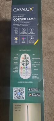
    There is no product URL that I can find anymore but the box looks like this:
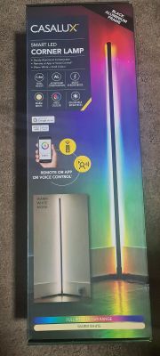
    Packaging of CasaLux Smart LED Corner Lamp with lamp graphics and features. Box of CasaLux Smart LED Corner Lamp.

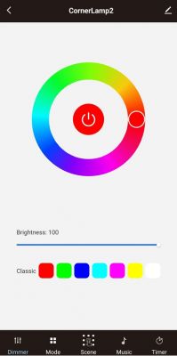
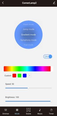
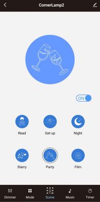
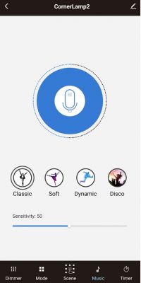
    After I added it to Tuya app this is what options are in it:
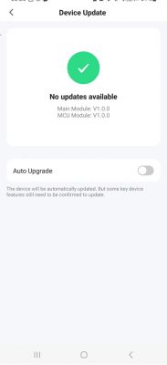
    Device update screen showing no updates available.

    App interface for controlling an LED lamp with a color wheel and brightness sliders.

    App interface for controlling a corner lamp with lighting modes and brightness adjustment.

    App interface with lighting settings for a corner lamp.

    Screenshot of the CornerLamp2 app interface controlling a corner lamp, with music mode options and sensitivity adjustment.

    The DP Ids I have found in Tuya IoT are:

    {
      "result": {
        "properties": [
          {
            "code": "switch_led",
            "custom_name": "",
            "dp_id": 20,
            "time": 1701165459278,
            "value": false
          },
          {
            "code": "work_mode",
            "custom_name": "",
            "dp_id": 21,
            "time": 1701163432151,
            "value": "dynamic_mod"
          },
          {
            "code": "colour_data",
            "custom_name": "",
            "dp_id": 24,
            "time": 1696248937973,
            "value": "003d03d40386"
          },
          {
            "code": "control_data",
            "custom_name": "",
            "dp_id": 28,
            "time": 1696232883464,
            "value": ""
          },
          {
            "code": "music",
            "custom_name": "",
            "dp_id": 102,
            "time": 1696247788543,
            "value": "424"
          },
          {
            "code": "RGB_order",
            "custom_name": "",
            "dp_id": 103,
            "time": 1701163432162,
            "value": 1
          },
          {
            "code": "LED_QTY",
            "custom_name": "",
            "dp_id": 104,
            "time": 1701163432172,
            "value": 30
          },
          {
            "code": "dynamic_mod",
            "custom_name": "",
            "dp_id": 106,
            "time": 1701163432151,
            "value": "043263000003e803e8007803e803e800f003e803e8"
          },
          {
            "code": "scene_mod",
            "custom_name": "",
            "dp_id": 108,
            "time": 1696247502001,
            "value": "CJ_YS"
          }
        ]
      },
      "success": true,
      "t": 1701276246105,
      "tid": "829cbbd58ed611ee83c62e7e80387ed3"
    }


    When turned on this is how the device works:


    After opening a few screws from the base I got to the PCB:
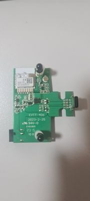
    Close-up of a PCB module labeled CYTI-406 on a white background.

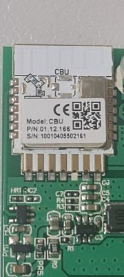
    And there is a CBU module:

    CBU module on a circuit board, technical markings visible

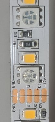
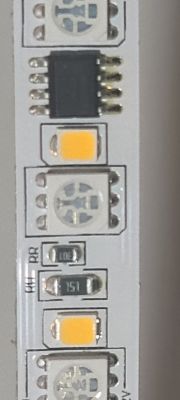
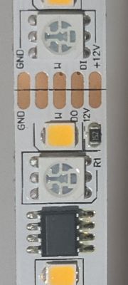
    Below are some pics of the led strip used in this device:
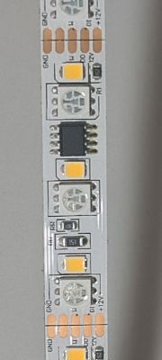
    WS2811 LED strip with a SOIC chip and 3 RGB LEDs.

    Close-up of an LED strip with pin labels and electronic components.

    Close-up of an LED strip with several diodes and a small integrated circuit.

    Close-up of an LED strip with visible components, including diodes and an integrated circuit.

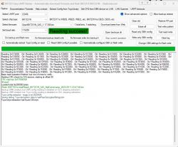
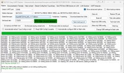
    Next got my hacking kit out and got a Tuya firmware backup (attached):
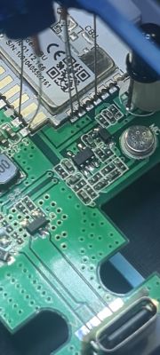
    Close-up of a PCB with a CBU module visible.

    Screenshot of BK7231N Easy UART Flasher software during data reading.

    OBK configuration extraction did not reveal anything useful - must be TuyaMCU in there somewhere :)
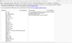
    Screenshot of BK7231 Easy UART Flasher software showing JSON configuration for a Tuya device.

    {
    	"abi":"0",
    	"id":"null",
    	"swv":"1.0.0",
    	"bv":"40.00",
    	"pv":"2.2",
    	"lpv":"3.3",
    	"pk":"didby1zofoliihp5",
    	"firmk":"null",
    	"cadv":"1.0.4",
    	"cdv":"1.0.0",
    	"dev_swv":"1.0.0",
    	"s_id":"null",
    	"dtp":"0",
    	"sync":"0",
    	"attr_num":"1",
    	"mst_tp_0":"9",
    	"mst_ver_0":"1.0.0",
    	"mst_tp_1":"0",
    	"mst_ver_1":"null",
    	"mst_tp_2":"0",
    	"mst_ver_2":"null",
    	"mst_tp_3":"0",
    	"mst_ver_3":"null }`)LAgw_wsm3&WAwf_start_mdll",
    	"md":"0",
    	"random":"0",
    	"wfb64":"1",
    	"stat":"0",
    	"token":"null",
    	"region":"null",
    	"reg_key":"null",
    	"dns_prio":"03{nc_tp",
    	"ssid":"null",
    	"passwd":"null",
    	"ap_passwd":"null",
    	"country_code":"null",
    	"bt_mac":"null",
    	"bt_hid":"null",
    	"prod_test":"false",
    	"fac_pin":"mzlyh8vz7p33qbz9 "
    }


    Sorry, no meaningful pins data found. This device may be TuyaMCU or a custom one with no Tuya config data.
    No module information found.
    And the Tuya section starts, as usual, at 2023424


    I have not flashed OBK to it yet.
    Just wanted to see first what is possible to do with this device.

    @p.kaczmarek2 - again looking for your guidance to see how I can config this device with OBK.

    Cool? Ranking DIY
    About Author
    MnM1
    Level 10  
    Offline 
    MnM1 wrote 169 posts with rating 11, helped 4 times. Been with us since 2023 year.
  • ADVERTISEMENT
  • #2 20838967
    p.kaczmarek2
    Moderator Smart Home
    Hello, can you check where is the data signal of LEDs connected? I think it may be connected to P16, which means there is a WIFI module driving LEDs directly, without TuyaMCU.
    Check Tuya docs to see where P16 is:
    https://developer.tuya.com/en/docs/iot/cbu-module-datasheet?id=Ka07pykl5dk4u
    Helpful post? Buy me a coffee.
  • #3 20838981
    MnM1
    Level 10  

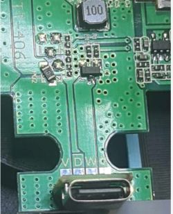
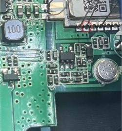
    The data pin seems to go into the unmarked black chip. Not sure if it goes to P16 (marked in red which actually is RX1) from there.

    Image of a green printed circuit board with electronic components and a USB-C port.

    Close-up of a green circuit board with visible electronic components. One pin is marked with a red circle.
  • #4 20838996
    p.kaczmarek2
    Moderator Smart Home
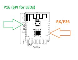
    You have marked RX, not P16. There is a difference between pin 16 on image and P16 of BK:
    Quote:

    2 P16 I/O Common GPIO, which can be reused as SPI_MOSI (Correspond to Pin 12 of the IC)

    P16 (SPI_MOSI) used to control LEDs directly is a pin 2 on the CBU image.
    Diagram of the CBU module with marked pins P16 and RX/P26.
    Helpful post? Buy me a coffee.
  • #5 20839014
    MnM1
    Level 10  
    I see what you mean - my bad

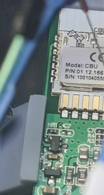
    There seems to be a trace coming out of P16:

    Close-up of an electronic circuit with a visible module and markings on the circuit board.

    Seems to be going to the black chip under HR1
  • ADVERTISEMENT
  • #6 20839019
    p.kaczmarek2
    Moderator Smart Home
    This is RGB + W device, right? So RGB LEDs are addressable and W is driven via PWM?
    Helpful post? Buy me a coffee.
  • #7 20839026
    MnM1
    Level 10  
    RGB LEDs are addressable. But not sure if W is PWM - how can I tell?

    The device is still hooked up - if you think there is something to work on I can flash it to OBK.
    I have a tuya backup as a last resort.... what do you think? Unless you think OBK doesnt support it yet.
  • #8 20839047
    p.kaczmarek2
    Moderator Smart Home
    Does the brightness of all white LED always change together? Or can it display different brightness levels per LED?

    I don't know if OBK supports it, I think we can do some short tests and then restore Tuya backup. Make sure that you have 2MB flash backup, it is very important so you can go back to Tuya later.
    Helpful post? Buy me a coffee.
  • #9 20839054
    MnM1
    Level 10  
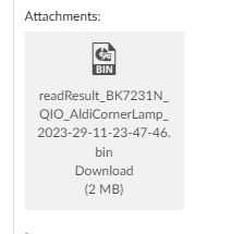
    As attached to the original post - I think I have the correct back up?

    Screenshot of a binary file attachment named readResult_BK7231N_QIO_AldiCornerLamp_2023-29-11-23-47-46.bin, size 2 MB.
  • #10 20839065
    p.kaczmarek2
    Moderator Smart Home
    It seems correct, you can try to flash OBK and for a good start play with GPIO doctor, maybe one of the pins is a simple PWM to control white level.

    There is 6 available PWMs on CBU, so there is not much choice.
    Helpful post? Buy me a coffee.
  • ADVERTISEMENT
  • #11 20839071
    MnM1
    Level 10  
    OK will do.

    I tried to dim the white light via Tuya app and all whites dimmed together.
    We will see what happens in OBK next :)

    BTW - so you dont end up waiting for me - Ill flash it and go to bed. Is 2AM here and gotta be up at 6AM for work :)
    I will let you know tomorrow the results from GPIO doctor.

    Thanks for your help!!

    Added after 4 [minutes]:

    Done.

    Screenshot of the BK7231 Easy UART Flasher program with a Write success! message.

    Off to bed.
    Talk tomorrow.
  • #12 20839120
    p.kaczmarek2
    Moderator Smart Home
    Once we finish testing with the GPIO doctor, we will also proceed to test the LEDs with current SM16703 driver. I tested it with WS2812 once, and it was somewhat working, but it wasn't perfect.
    Helpful post? Buy me a coffee.
  • #13 20839555
    MnM1
    Level 10  

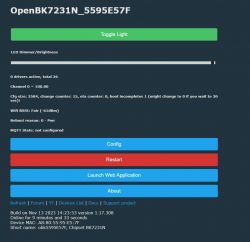
    GPIO Doctor shows that PIN6 = PWM.
    It controls the white color.

    Screenshot of OpenBK7231N interface with configuration and restart buttons and device status information.

    Toggle and brightness work fine.
  • #14 20839562
    p.kaczmarek2
    Moderator Smart Home
    Ok, now try:

    1. Start driver
    startDriver SM16703P

    2. Init Driver - replace 64 with number of LEds
    SM16703P_Init 64

    3. Set Pixel
    SM16703P_SetPixel 1 255 0 0
    SM16703P_SetPixel 2 0 255 0
    SM16703P_SetPixel 3 0 0 255

    4. Start Output (each call will trigger one)
    SM16703P_Start
    Helpful post? Buy me a coffee.
  • #15 20839565
    MnM1
    Level 10  

    OK, I get this:

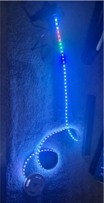
    LED strip on the floor with multicolored lights.

    The first 3 LEDs are cool white.
    The second lot of 3 LEDs are RED.
    The third lot of LEDs are GREEN.
    The fourth lot of LEDs are BLUE.

    The rest of the LEDs are cool white.
  • #16 20839567
    p.kaczmarek2
    Moderator Smart Home
    You can try script from this post:
    https://www.elektroda.com/rtvforum/topic3968310.html#20734037
    So the proof of concept works...
    Helpful post? Buy me a coffee.
  • #17 20839570
    MnM1
    Level 10  

    OK, if I add that code below to autoexec.bat, I restart the device and nothing happens.
    I think I am doing something wrong.

    setChannel 10 1
    again:
    addChannel 10 1
    SM16703P_SetPixel $CH10-2 0 0 255
    SM16703P_SetPixel $CH10-1 0 255 0
    SM16703P_SetPixel $CH10 255 0 0
    SM16703P_Start
    delay_s 0.5
    goto again


    Added after 15 [minutes]:

    Changed the autoexec.bat to:

    startDriver SM16703P
    SM16703P_Init 87
    SM16703P_SetPixel 1 255 0 0
    SM16703P_SetPixel 2 0 255 0
    SM16703P_SetPixel 3 0 0 255
    setChannel 10 1
    again:
    addChannel 10 1
    SM16703P_SetPixel $CH10-2 0 0 255
    SM16703P_SetPixel $CH10-1 0 255 0
    SM16703P_SetPixel $CH10 255 0 0
    SM16703P_Start
    delay_s 0.5
    goto again


    This got the script running.

    However, it is not working as it should.

    - The first 4 sets of 3 LEDs are always white.
    - While 3 colors "travel" through the LEDs (not always the same 3 colors, they do change during the loops), the whites are changing (sometimes to purple, other times to blue).
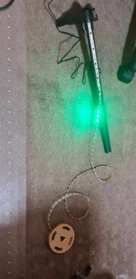
    - Not sure if this loop was supposed to be forever, but after completing a few loops, the device got stuck on this:

    LED strip with glowing green LEDs placed on a carpet.

    Added after 11 [minutes]:

    Did a bit more testing.
    After the loop completes the first time, it leaves the first 5 sets of 3 LEDs as white, while the rest of the LEDs are blue.

    Added after 6 [minutes]:

    If I put the exact number of LEDs I have (90), the loop completes once, leaving behind the first 5 sets of 3 LEDs as white, while the rest of the LEDs are blue.
    Then it waits a long while and does a second loop, leaving all the LEDs blue.
    After that, it seems to do nothing at all.

    If I put 87 as the number of LEDs, the loop seems to be going a few more times, but then it seems to be crashing on green, as mentioned before. Also, it does strange things like it seems to loop on the 7th set of 3 LEDs only, before crashing on green.

    Also, the "travelling" LEDs - the RED seems to be purple, not red. Green and blue are OK.
  • #18 20850074
    MnM1
    Level 10  

    @p.kaczmarek2 - Would you have some time to see if we can progress the work on this?

    Cheers :)
  • #19 20850252
    p.kaczmarek2
    Moderator Smart Home
    I will try to look into it soon, but today I am finishing RN8209C driver:
    https://www.elektroda.com/rtvforum/topic4014818.html#20840241
    On your side, I will most likely first do that CW/RGB separation option as it's way easier than LEDs, I would have to hook up scope for that.
    Helpful post? Buy me a coffee.
  • #20 20884322
    MnM1
    Level 10  
    Hi @p.kaczmarek2 - any progress on this yet?
  • #21 20963683
    MnM1
    Level 10  
    Hi @p.kaczmarek2 - any more progress with this device?
  • #22 20963738
    p.kaczmarek2
    Moderator Smart Home
    Individually addressable LEDs have been more or less fixed yesterday, can you update and recheck if they work more stable now?
    See related topic: https://www.elektroda.com/rtvforum/topic4033333.html#20961957
    Helpful post? Buy me a coffee.
  • #23 20966217
    p.kaczmarek2
    Moderator Smart Home
    The SPI DMA driver bug has been fixed. The SM16703P/WS2812B/etc LEDs should work good now. Please update your devices. For scripting configuration, please see:
    OpenBeken WS2812B driver (compatible with SM16703P, etc) - short scripting presentation
    We can continue discussion there. The more advanced animation will be added soon, stay tuned!
    Helpful post? Buy me a coffee.
  • #24 20966864
    MnM1
    Level 10  
    Thanks - that's great progress. I will test soon.
  • #25 21286785
    MnM1
    Level 10  
    Hi @p.kaczmarek2

    I stared testing this corner lamp with Pixel Animation.

    I am on the latest firmware - 1.17.764 for BK7231N

    My startup.bat is:

    startDriver SM16703P
    SM16703P_Init 90
    startDriver PixelAnim


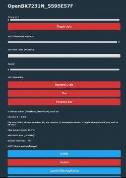
    The web page loads and it looks like:

    Control interface for LED lamp with animation features on OpenBK7231N.

    However the animation is not quiet OK for me. This is how the fire animation behaves:


    Not sure about the whites on this item - if I enable Flag 4 and I move the Color Temp slider all leds go off.
    The video above was done without any Flags enabled.

    Can you please see if you can workout what the issue can be?

    Many thanks.
  • #26 21307717
    MnM1
    Level 10  
    Hi @p.kaczmarek2 - did you manage to look at the video I posted? If there is a fix please let me know so I can try it.
  • #27 21307849
    p.kaczmarek2
    Moderator Smart Home
    Hello, does setting red, blue and green colors through the web interface works correctly? What happens if you try to set colors via commands, let's say, first turn off the LEDs, then set first color to red, second to green, third to blue?
    Helpful post? Buy me a coffee.
  • ADVERTISEMENT
  • #28 21308133
    MnM1
    Level 10  
    I have tried from the web interface - the colors seem to be changing OK.
    However, when I have tried from GUI:

    SM16703P_SetPixel all 0 0 255
    or
    SM16703P_SetPixel all 0 255 0
    or
    SM16703P_SetPixel all 255 0 0

    nothing happens.
  • #29 21328668
    MnM1
    Level 10  
    Hi @p.kaczmarek2 - I am not sure if you saw my reply above yet.
  • #30 21384459
    MnM1
    Level 10  
    Hi @p.kaczmarek2 - any chance to look at this and see why is not working as it should?

Topic summary

The discussion revolves around the teardown and functionality of the Aldi (Australia) CasaLux Smart LED Corner Lamp, utilizing the BK7231N chip. Users explore the connections of the LED data signal, identifying the P16 pin for controlling RGB LEDs directly. The RGB LEDs are confirmed to be addressable, while the white LEDs' control via PWM is tested. Users share their experiences with flashing the device to OpenBeken (OBK) firmware, testing GPIO functionality, and scripting for LED animations. Issues with LED behavior during animations and brightness control are addressed, with ongoing improvements noted in the firmware updates for better stability and performance of the SM16703P driver.
Summary generated by the language model.
ADVERTISEMENT