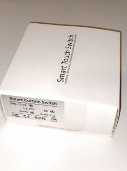
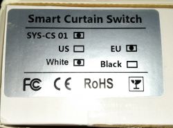
I bought this TEEPAO WI-FI Curtain Switch as second hand. It is designed for controlling electric curtains as its name says. One button for opening, one stop button, and one for closing curtains. It has controllable backlight. As I do not have such curtains I configured it to be as switch with 2 buttons and one extra button. This is the box:

Front: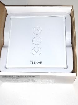
Back: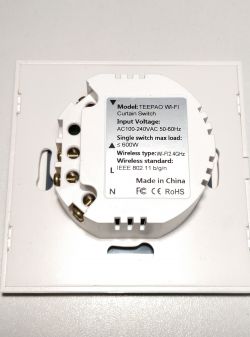
To open the switch, one has to use some sharp tool:
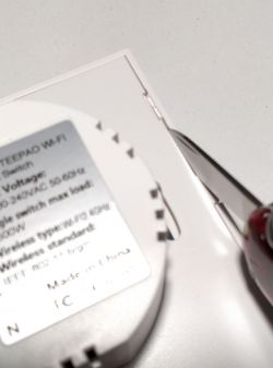
The button plate is softly glued to the case with foam pieces. It can be easily removed like that:
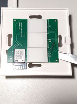
A closer look:
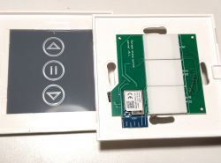
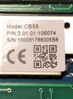
It has CB3S wifi module:
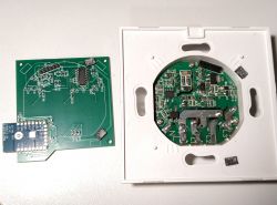
After removing the button plate one can see the back of button plate and solder side of power plate:
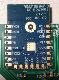
Here is the pinout of wifi module:
To get out the power part one has to remove wire screws:
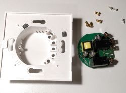
Closer look of both sides of the power plate:
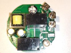
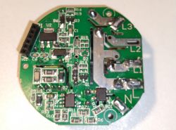
I tried to flash the device with tuya-cloudcutter without success. So I had to use wiring.
Wiring to flash the device.
The pins connecting the button plate with power plate has GND and 3.3V pins, so those do not have to be soldered. RX and TX have to be soldered. RX pin is connected to button control chip and this does not allow to flash new firmware. One has to desolder the button control chip pin 16 or cut through the wire between RX and this chip. There is always possibility also to remove the whole wifi plate or button control chip of course.
I chose to desolder the pin 16 only:
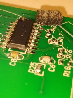
For flashing I used HW-597 USB to TTL module with CH340G chip. The power of this module was too weak to power the button plate, so I used a 5V to 3.3V power converter. I have had no such problem with PL2302 module.
The pinout of HW-597 module from left to right is:
5V (power)
VDD (for choosing 5V or 3.3V TTL output)
3V3 (power)
TXD
RXD
GND
As I told, the GND and 3.3V can be reached on pins of button plate <-> power plate connector. Pin 2 is ground and Pin 1 is 3.3V. Pin 2 is connected to HW-597 ground pin, Pin 1 is connected to AMS1117 5V to 3.3V converter chip which is soldered to the back of the power interruption switch (for initializing flashing). AMS1117 needs also the ground, so it is connected to ch-597 ground with a wire. RXD and TXD of wifi board are soldered to TXD and RXD of HW-597.
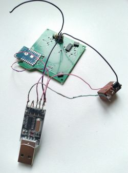
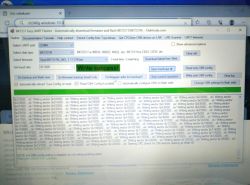
I used BK7231 Easy UART Flasher. This software runs under Microsoft Windows. Fortunately my kid has one. At first windows did not recognize the usb to ttl converter and I started to search for it, but after a while the driver got installed without any special download. The flasher worked without any problems. Sorry for blurry picture. Forgot to focus.
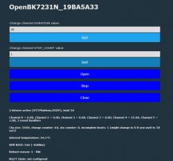
After restart OpenBK booted up and I configured buttons, backlight and green led to be sure all are available. I will not go through this process, as I will provide json template where everything is already configured.
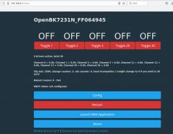
This configuration allows to use the device as 2 way switch, while in ON state buttons glow. Middle button switches only its light and can be configured to do something else. Maybe switching both relays at the same time on or off. Backlight and green led can be only controlled from web with this config.
Configuration json is attached:


Front:

Back:

To open the switch, one has to use some sharp tool:

The button plate is softly glued to the case with foam pieces. It can be easily removed like that:

A closer look:

It has CB3S wifi module:

After removing the button plate one can see the back of button plate and solder side of power plate:

Here is the pinout of wifi module:

To get out the power part one has to remove wire screws:

Closer look of both sides of the power plate:


I tried to flash the device with tuya-cloudcutter without success. So I had to use wiring.
Wiring to flash the device.
The pins connecting the button plate with power plate has GND and 3.3V pins, so those do not have to be soldered. RX and TX have to be soldered. RX pin is connected to button control chip and this does not allow to flash new firmware. One has to desolder the button control chip pin 16 or cut through the wire between RX and this chip. There is always possibility also to remove the whole wifi plate or button control chip of course.
I chose to desolder the pin 16 only:

For flashing I used HW-597 USB to TTL module with CH340G chip. The power of this module was too weak to power the button plate, so I used a 5V to 3.3V power converter. I have had no such problem with PL2302 module.
The pinout of HW-597 module from left to right is:
5V (power)
VDD (for choosing 5V or 3.3V TTL output)
3V3 (power)
TXD
RXD
GND
As I told, the GND and 3.3V can be reached on pins of button plate <-> power plate connector. Pin 2 is ground and Pin 1 is 3.3V. Pin 2 is connected to HW-597 ground pin, Pin 1 is connected to AMS1117 5V to 3.3V converter chip which is soldered to the back of the power interruption switch (for initializing flashing). AMS1117 needs also the ground, so it is connected to ch-597 ground with a wire. RXD and TXD of wifi board are soldered to TXD and RXD of HW-597.

I used BK7231 Easy UART Flasher. This software runs under Microsoft Windows. Fortunately my kid has one. At first windows did not recognize the usb to ttl converter and I started to search for it, but after a while the driver got installed without any special download. The flasher worked without any problems. Sorry for blurry picture. Forgot to focus.

After restart OpenBK booted up and I configured buttons, backlight and green led to be sure all are available. I will not go through this process, as I will provide json template where everything is already configured.

This configuration allows to use the device as 2 way switch, while in ON state buttons glow. Middle button switches only its light and can be configured to do something else. Maybe switching both relays at the same time on or off. Backlight and green led can be only controlled from web with this config.
Configuration json is attached:
Cool? Ranking DIY


