logo elektroda
logo elektroda
X
logo elektroda

Reversing PWM Output Logic for P-Channel MOSFETs on WB8P (BK7231T) Module

apsis 168 7
ADVERTISEMENT
  • #1 21586592
    apsis
    Level 6  
    Hello,

    I created my own Night light with all custom parts and wb8p (BK7231T) module.

    However I selected P-channel mosfets for the led control.

    Can anyone advise me on how to reverse PWM so LOW (0v) is the on state?
    I really prefer not to build level inversion circuit, as it just seems dumb.

    There are some additional questions on how to read the Light sensor connected to ADC, but this is not as urgent.

    Added after 44 [minutes]:

    Chat GPT told me to go OpenBeken 1.19.x i did find compiled thing and it was horrible.

    Guess i either spend time soldering or wait.

    I am amazed such simple thing is not there yet...

    Added after 9 [minutes]:

    I use SOT-23 mosfets, so this is another hell to solder with no PCB, well i guess i have to,
  • ADVERTISEMENT
  • Helpful post
    #2 21586648
    p.kaczmarek2
    Moderator Smart Home
    I think there is already PWM_n role in OpenBeken, exactly for this purpose.

    Added after 37 [seconds]:


    Reversing PWM Output Logic for P-Channel MOSFETs on WB8P (BK7231T) Module
    Helpful post? Buy me a coffee.
  • ADVERTISEMENT
  • #3 21586683
    apsis
    Level 6  
    >>21586648 Well, turns out me and ChatGPT both did not find this - THANKS!!!

    Now will look for a way to make the light sensor (photo-resistor in voltage divider setup) work.
    Any advice is welcomed!
  • #4 21586692
    p.kaczmarek2
    Moderator Smart Home
    Did you point ChatGPT towards our docs? It should be able to open few pages. I will check this in a moment.


    Well, BK7231 chips has one ADC pin that you can use in OBK. WB8P seem to have it marked on the silkscreen. OBK has ADC role that can read ADC value to channel. Then you can process it with scripting, depending on what you want to achieve..

    Btw, how your current board looks like? I also did some DIY dimmers in the past so I am curious.
    Helpful post? Buy me a coffee.
  • #5 21586729
    apsis
    Level 6  
    >>21586692
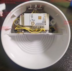
    There is NO board, it's a SMD wire web held up with UV resin.
    I use custom Led arrays (one made from orange car blinker leds (PWM5), and one from cold white solar lamp(PWM1)) with appropriate current limiting (22 ohm resistor for cold white and just diode to drop 0.2v for orange).
    Do not worry they run well under 50% rated current, yellow ones are even on ALU PCB even though they are running at 60mA for 5 5730 leds.
    all leds are running off same power as MCU : 3.3v : https://www.aliexpress.com/item/1005006368811....order_list.order_list_main.69.38c61802S4btol

    I use si2301 as led control led with 20k pull up.
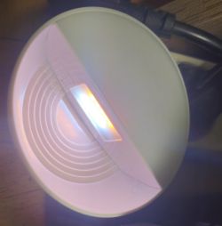
    The body is Chinese night lamp.

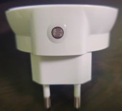
    Light sensor is photo resistor i gt from who knows where...
    seems 1.5Mohm resistor was nice match match for it /or highest i had/ so now i read 3000lux at very dark at 2700 at dark when i configure the ADV as lux sensor.

    Still no idea what script i need

    Added after 23 [minutes]:

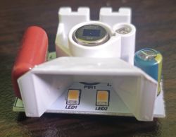
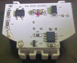
    Here are some pictures.
    Last two are original board.

    Reversing PWM Output Logic for P-Channel MOSFETs on WB8P (BK7231T) Module
    Reversing PWM Output Logic for P-Channel MOSFETs on WB8P (BK7231T) Module
    Reversing PWM Output Logic for P-Channel MOSFETs on WB8P (BK7231T) Module
    Reversing PWM Output Logic for P-Channel MOSFETs on WB8P (BK7231T) Module
    Reversing PWM Output Logic for P-Channel MOSFETs on WB8P (BK7231T) Module
  • ADVERTISEMENT
  • #6 21587320
    apsis
    Level 6  
    I checked ALL I could find - no idea where to place script and autoexec.bat does not seem to support actions based on ADC read value.
    Any help ?
  • Helpful post
    #7 21587325
    p.kaczmarek2
    Moderator Smart Home
    Hey sorry for delay. Are you able to get ADC value to channel?

    If you are, then you can do:
    
    addChangeHandler Channel3 > 500 SetChannel 1 0
    addChangeHandler Channel3 <= 500 SetChannel 1 1
    

    or also:
    
    again:
    if $CH4>=500 then SetChannel 1 1
    delay_s 0.1
    goto again
    

    etc
    Helpful post? Buy me a coffee.
  • ADVERTISEMENT
  • #8 21587347
    apsis
    Level 6  
    yes I managed to read the ADC by setting it to illuminate and channel 3.
    Output is inverted, but this is fine with me.

    Your commands did work!
    Thank you so much I scraped throughout all documentation and could not find this, was expecting to use GetChannel

    Added after 10 [minutes]:

    This did the trick for me:

    addChangeHandler Channel3 > 2900 led_enableAll 1
    addChangeHandler Channel3 <= 2700 led_enableAll 0

    My readings are inverted due to wiring

Topic summary

A custom night light project using the WB8P module with a BK7231T chip and P-channel MOSFETs for LED control required reversing the PWM output logic so that a LOW (0V) signal turns the LEDs on. Instead of adding an external level inversion circuit, the solution was found within the OpenBeken firmware, which supports a PWM_n role designed for inverted PWM signals. The user also integrated a photoresistor light sensor connected to the ADC pin on the BK7231T, configured as a voltage divider with a 1.5 MΩ resistor. Reading ADC values was achieved by assigning the ADC role to a channel in OpenBeken and using scripting commands such as addChangeHandler to trigger LED control based on light intensity thresholds. The user successfully implemented scripts to enable or disable LEDs depending on ADC readings, despite the inverted output due to wiring. The discussion highlights the use of SOT-23 P-channel MOSFETs (specifically the SI2301) with a 20k pull-up resistor, custom LED arrays (orange car blinker LEDs and cold white solar lamp LEDs), and the challenges of soldering without a PCB. The OpenBeken 1.19.x firmware was recommended for these features, and scripting was essential for ADC-based automation.
Summary generated by the language model.
ADVERTISEMENT