logo elektroda
logo elektroda
X
logo elektroda

[Solved] How to avoid the problem with the ESP8266 V3 and the reed switch on pin D8?

szyba20 579 9
ADVERTISEMENT
Treść została przetłumaczona polish » english Zobacz oryginalną wersję tematu
  • #1 20929024
    szyba20
    Level 19  
    Hello
    As in the subject, I have a module esp8266 to control a garage door with a reed switch sensor,
    everything works as expected until the power goes out :/ and the board does not want to start if it has a high state on the D8 pin (reed switch connected)
    Please suggest how to do it differently or how you connect it,
  • ADVERTISEMENT
  • ADVERTISEMENT
  • #3 20929047
    szyba20
    Level 19  
    Ehhh... shame on me... , please tell me under which pin it is best to connect it which supports high state ? I have checked D4 D6 D7 and it does not work and I have little to do with esp8266.... and I don't really understand...
  • #4 20929062
    jarekgol
    Level 39  
    I too have little in common after a few adventures. When I don't need wifi I go for the old AVRs :) from this spread it looks like D6 D7 should work, as long as you're not using SPI
    Since you're using D and not GPIO designations, I assume some Arduino, write what exactly the board is then maybe someone can tell you more.
  • ADVERTISEMENT
  • #5 20929069
    szyba20
    Level 19  
    I don't use SPI but I can't drive any other input low or high except D8 :/
    I bought the boards from one seller on All signed as esp8266 V3 that's all I know about them :)
    after changing the code the board seems dead on states on other inputs.... I changed to other inputs the same... so probably I do something not as the manufacturer predicted :)

    as for designations I use D because such descriptions have the board to not get lost :) in the code gives
    - platform: gpio
    pin:
    number: D8
  • Helpful post
    #6 20929108
    jarekgol
    Level 39  
    You can connect an led or voltmeter to these others, write some flashing, but with the input mode set and see if maybe changing the mode doesn't work?
    Have you got a resistor in there for that reed switch (as a pull-down)?

    Well, in situations like this, it's good to fire up a new 'sketch' without the various libraries and check the operation of the ports on it.
  • #7 20929115
    szyba20
    Level 19  
    I've just come across the same thing ^^ I was looking at a voltage divider that I'm making for another board iii ehh I've been messing around again instead of putting 10k pulled up to GND and seeing what happens then and it will probably work I've been messing around for 2h :) Thank you for your help I'll check tomorrow to see if it works :)
  • #8 20930686
    @GUTEK@
    Level 31  
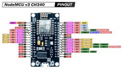
    I don't play with the ESP8266 too much, but from what you describe I think you have a NodeMCU v3.
    It also has the SD card support pins brought out. What if you used any of them, they seem "more normal" than the basic ones.

    These are the ones on the left from GPIO6 to 11:
    NodeMCU v3 CH340 pinout diagram with GPIO pins 6 to 11 highlighted on the left side. .
  • ADVERTISEMENT
  • #9 20931740
    szyba20
    Level 19  
    thanks for your help, I managed by adding 10k on GND relative to the input as a pull-down and everything started and no problems on reset :)

Topic summary

The discussion revolves around issues faced with the ESP8266 V3 module when using a reed switch connected to pin D8. The main problem arises when the board does not boot if D8 is in a high state after a power outage. Suggestions include using different GPIO pins (D6, D7) that may not conflict with SPI, and the importance of implementing a pull-down resistor (10k) to ensure proper booting. The user successfully resolved the issue by adding a pull-down resistor to ground, allowing the board to reset without problems.
Summary generated by the language model.
ADVERTISEMENT