logo elektroda
logo elektroda
X
logo elektroda

BK7231T/WB3S - Martin Jerry - 2 Gang Tuya Switch - Configuration needed

DCG 579 2
ADVERTISEMENT
  • #1 20992899
    DCG
    Level 6  
    Hey All,

    Couple of months back I had purchased a 2 Gang Tuya switch from Amazon India website and today I was in a mood to check if the device is OBK compatible via cloud cutter, to my surprise the Cloud cut worked fine, and I was able to flash OBK (used Tuya Genric DS 102 2Gang profile) to flash OBK.

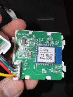
    I am now stuck since the device could be Tuya MCU WB3S and unable to identify DpIDs and Pins.

    https://www.amazon.in/gp/product/B0CGF3RY2Q/ref=ppx_yo_dt_b_asin_title_o00_s00?ie=UTF8&psc=1
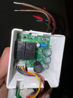
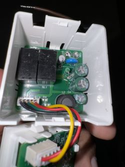
    Close-up of the inside of a 2 Gang Tuya switch with visible electronic components. Inside of a Tuya 2 Gang switch showing exposed circuit board and wires. Close-up of a circuit board with a WB3S module.
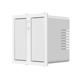
    White 2 Gang Tuya wall switch with a minimalist design.

    Please need help
  • ADVERTISEMENT
  • #2 20992995
    p.kaczmarek2
    Moderator Smart Home
    I don't think it's TuyaMCU because I can't see RX/TX pins of WB3S soldered anywhere.

    Can you try to open Web App and use the GPIO Doctor there to find the roles of the GPIO? Start with relays.

    Alternatively, try to automatic GPIO extraction:


    Helpful post? Buy me a coffee.
  • Helpful post
    #3 20994054
    DCG
    Level 6  

    p.kaczmarek2 wrote:
    I don't think it's TuyaMCU because I can't see RX/TX pins of WB3S soldered anywhere.

    Alternatively, try to automatic GPIO extraction:


    Hey, the GPIO extraction tool did the trick, and the device is now working perfectly... :)

    Below is the template, please add it

    {
      "vendor": "Tuya",
      "bDetailed": "0",
      "name": "Martin Jerry 2 Gang Smart Wall Switch",
      "model": "Martin Jerry 2 Gang Switch",
      "chip": "BK7231T",
      "board": "TODO",
      "flags": "1024",
      "keywords": [
        "TODO",
        "TODO",
        "TODO"
      ],
      "pins": {
        "1": "WifiLED_n;0",
        "6": "Rel;1",
        "8": "Btn;2",
        "14": "Btn;1",
        "24": "Rel;2"
      },
      "command": "",
      "image": "https://m.media-amazon.com/images/I/51sbTxJ1uWL._SL1500_.jpg",
      "wiki": "https://www.elektroda.com/rtvforum/topic4040836.html


    Script which can be imported

    ClearIO // clear old GPIO/channels
    lfs_format // clear LFS
    StartupCommand ""  // clear STARTUP
    stopDriver *  // kill drivers
    backlog setPinRole 1 WifiLED_n; setPinChannel 1 0
    backlog setPinRole 6 Rel; setPinChannel 6 1
    backlog setPinRole 8 Btn; setPinChannel 8 2
    backlog setPinRole 14 Btn; setPinChannel 14 1
    backlog setPinRole 24 Rel; setPinChannel 24 2
    Flags 1024
ADVERTISEMENT