First of all, I would like to praise the SUPER Forum and all its super members
I've been interested in getting all my light switches off the cloud for a while now, and using OPENBK for some where I can't use Tasmota
One of them is Bingoelec Wifi Touch Switch 3Gang With Normal EU Socket Without Wifi 3 Color Crystal Glass Panel Smart Switch
LINK
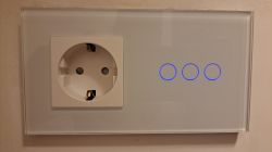
Turns out the switch is actually Bingoelec 1/2/3/4 Gang WiFi Smart Touch Switch Accessories Neutral Live Wire Switch Function Keys DIY Part EU Standard Base
LINK
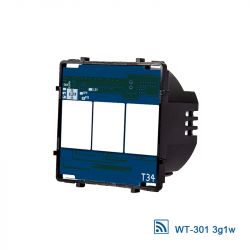
I flashed it with the following software: BK7231GUIFlashTool
Pins on the Bingoelec 3 Gang Standard Base are as follows:
P10 - RX
P11 - TX
GND
3.3V
CEN (it didn't work for me, so I just did ON-OFF)
Some pictures of me while I was flashing:
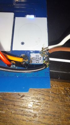
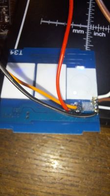
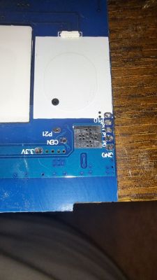
I had to carefully remove one of the master plates in order to have access to P10 and P11
I used the information from the link: LINK
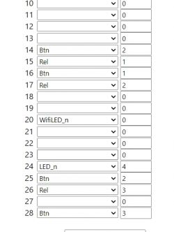
Pin 24 has the ability to turn on or off the LED Backlight switch.
I hope I saved someone time and trouble.
PS: this is my first topic, so if there are any mistakes, I apologize, and I would ask the administrators to correct them. Thank you
I've been interested in getting all my light switches off the cloud for a while now, and using OPENBK for some where I can't use Tasmota
One of them is Bingoelec Wifi Touch Switch 3Gang With Normal EU Socket Without Wifi 3 Color Crystal Glass Panel Smart Switch
LINK

Turns out the switch is actually Bingoelec 1/2/3/4 Gang WiFi Smart Touch Switch Accessories Neutral Live Wire Switch Function Keys DIY Part EU Standard Base
LINK

I flashed it with the following software: BK7231GUIFlashTool
Pins on the Bingoelec 3 Gang Standard Base are as follows:
P10 - RX
P11 - TX
GND
3.3V
CEN (it didn't work for me, so I just did ON-OFF)
Some pictures of me while I was flashing:


I had to carefully remove one of the master plates in order to have access to P10 and P11
I used the information from the link: LINK
{
  "vendor": "Tuya",
  "bDetailed": "0",
  "name": "Bingoelec DIY Series Smart WiFi Wall Touch Switch Base",
  "model": "DIY Series Smart WiFi Wall Touch Switch 3 gang",
  "chip": "T34 Tuya(BK7231N)",
  "board": "TW2-0003A",
  "flags": "1088",
  "keywords": [
    "Bingoelec",
	"DAJIMEI",
	"T34",
	"TW2-0003A"
  ],
  "pins": {
    "14": "Btn;2",
    "15": "Rel;1",
    "16": "Btn;1",
    "17": "Rel;2",
    "20": "WifiLED_n;0",
    "24": "LED_n;4",
    "25": "Btn;2",
    "26": "Rel;3",
    "28": "Btn;3"
  },
  "command": "",
  "image": "https://obrazki.elektroda.pl/1582514300_1695766732.jpg",
  "wiki": "https://www.elektroda.com/rtvforum/topic_YOUR_TOPIC.html"
}
Pin 24 has the ability to turn on or off the LED Backlight switch.
I hope I saved someone time and trouble.
PS: this is my first topic, so if there are any mistakes, I apologize, and I would ask the administrators to correct them. Thank you


