![[BK7231] Martin Jerry Single Pole Smart Switch US-SS01 Flashing Guide & Template GPIO [BK7231] Martin Jerry Single Pole Smart Switch US-SS01 Flashing Guide & Template GPIO](https://obrazki.elektroda.pl/6548597000_1690263113_thumb.jpg)
This switch was actually pretty easy to figure out and flash/configure thanks to the OpenBK team. I am mainly using the Feit Smart Dimmer switches as my local Costco had the $.00 manager clearance sale on them for $7 for a 2 pack a few months ago. So I bought all 13 2 packs they had left. Now nearly every light switch is smart and dimmable in my house. Thanks bleeblak8 for figuring out that one to get me started and have some foundation to figure out this one.
I wanted to control a few fans and could not easily figure out how to disable the dimmer safely, so I bought a 4 pack of Martin Jerry switches for $52 (almost 4x what I paid for the Feit ones lol) as it seemed like they were all cheap ESP devices that I could easily flash tasmota on, but the US-SS01 has the WB2S WiFi board instead. This is the same BK7231 in the Feit so I poked around to see if I could easily flash it. Turns out it was very easy to open and flash. Took me about 3 hours to figure this all out.
![[BK7231] Martin Jerry Single Pole Smart Switch US-SS01 Flashing Guide & Template GPIO [BK7231] Martin Jerry Single Pole Smart Switch US-SS01 Flashing Guide & Template GPIO](https://obrazki.elektroda.pl/6548597000_1690263113_thumb.jpg)
![[BK7231] Martin Jerry Single Pole Smart Switch US-SS01 Flashing Guide & Template GPIO [BK7231] Martin Jerry Single Pole Smart Switch US-SS01 Flashing Guide & Template GPIO](https://obrazki.elektroda.pl/4683536600_1690483611_thumb.jpg)
All the plastic is held together by tabs so it is easily removed. All we need to do is pop off the button.
![[BK7231] Martin Jerry Single Pole Smart Switch US-SS01 Flashing Guide & Template GPIO [BK7231] Martin Jerry Single Pole Smart Switch US-SS01 Flashing Guide & Template GPIO](https://obrazki.elektroda.pl/2730632500_1690483637_thumb.jpg)
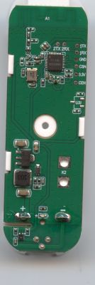
Now the little board that is sticking out on the top right is the WB2S, luckily everything we need is accessible from this side of the board. Here is the pin out if you want to get a better feel of what we are doing.
![[BK7231] Martin Jerry Single Pole Smart Switch US-SS01 Flashing Guide & Template GPIO [BK7231] Martin Jerry Single Pole Smart Switch US-SS01 Flashing Guide & Template GPIO](https://obrazki.elektroda.pl/9768841400_1690263213_thumb.jpg)
![[BK7231] Martin Jerry Single Pole Smart Switch US-SS01 Flashing Guide & Template GPIO [BK7231] Martin Jerry Single Pole Smart Switch US-SS01 Flashing Guide & Template GPIO](https://obrazki.elektroda.pl/6018665600_1690263415_thumb.jpg)
3.3v (VBAT), GND, RX, TX are all facing the LEDs, from the bottom up. We will need to solder leads to each of them or you might even be able to use thin alligator clips as the pins are zig-zagged with gaps or just insulate the other side from making contact. If you are worried about melting the plastic or want more room to work you can completely take the board out. All you have to do is undo 4 tabs between the plate that goes on the wall and the back part of the unit. I did this for my first one as I was figuring it out, but the other 3 I did not.
![[BK7231] Martin Jerry Single Pole Smart Switch US-SS01 Flashing Guide & Template GPIO [BK7231] Martin Jerry Single Pole Smart Switch US-SS01 Flashing Guide & Template GPIO](https://obrazki.elektroda.pl/9828712900_1690483661_thumb.jpg)
Now RX is connected to the main board and it will not flash if it is. I used a solder sucker and my iron to remove the connection and add a little back to the WiFi board so I can connect my lead. Other solder removal tricks like a wick should work here too. Hopefully you can see this in my photo below. I would do this connection first.
![[BK7231] Martin Jerry Single Pole Smart Switch US-SS01 Flashing Guide & Template GPIO [BK7231] Martin Jerry Single Pole Smart Switch US-SS01 Flashing Guide & Template GPIO](https://obrazki.elektroda.pl/4453401000_1690263775_thumb.jpg)
You will need 2 leads for ground as you will have to momentary ground CEN on the other side to get into flashing mode. In the photo below the blue lead is actually touching the very top pad, but only looks like it is on the 2nd from the top. The other side is stabbed in the back of the ground lead. You could use a button to make this very easy to get timing correct during flashing.
![[BK7231] Martin Jerry Single Pole Smart Switch US-SS01 Flashing Guide & Template GPIO [BK7231] Martin Jerry Single Pole Smart Switch US-SS01 Flashing Guide & Template GPIO](https://obrazki.elektroda.pl/2229773700_1690264473_thumb.jpg)
Once you are all soldered we are ready to flash.
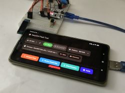
Download the latest OpenBK7231 flasher https://github.com/openshwprojects/BK7231GUIFlashTool/releases
Select BK7231T under chip type
Click download latest from web
Plug in your USB to UART. Connect the 3.3v, ground, RX and TX (remember RX from the board goes to TX on the USB UART and TX to RX) Do not have anything else connected while flashing or working on the board!
Click either "Do backup and flash new" or "Do firmware write (no backup!)". I do the 2nd as I will not need the old firmware again.
Now it is going to have some yellow text asking you to restart the device. This is when you connect CEN to ground for about a second. Getting the timing is the hardest part. It took me a few times and I accidentally did it again while it was erasing. If it has already erased part of it you should no longer need to do this as it will just connect and flash automatically.
Once it is done flashing remove power from the device and re-power it. You can put it back together now, but I like to make sure it flashed correctly first. Once you power it back up you should see a new open WiFi network like OpenBK7312T_XXXXX with the Xs being something else. Once connected go to 192.168.4.1 in your browser.
I configure WiFi first so I can get internet back on my laptop again right away. So go to "Config" -> "Configure WiFi" and then type in your WiFi SSID and Password. This device is 2.4ghz only so make sure the network your connecting to is 2.4ghz. Now it will try to connect to your network. Login to you router and find the switches IP address. It will be named the same thing as it's network was. Type in the new IP and it should take you back to the same main screen again.
In the Web App of OpenBK there is a way to select a device to auto populate the pin config, but I am not sure how to add this switch to that right now so you will have to manually do it. The switch will not function at all if you don't do this. Click "Config" -> "Configure Module" and enter the following:
P8 "Rel" 1
P10 "Btn" 1
P24 "WiFiLED"
P26 "LED_n" 1
Click save at the bottom and it is all ready to go now! When you are ready to put it back together just unsolder all the leads and reconnect RX to the main board again.
This config is set up so that when it is trying to connect to WiFi a red LED will flash, but be off once it does. If you want it to be on while connected to WiFi select "WiFiLED_n" instead. It is also set up so that while the switch is off the blue LED will be off, and while it is on the blue LED will be on. You can invert this by selecting "LED" instead. You can switch the colors by flipping the setting between 24 and 26 too or completely disable them by selecting nothing on either or both. Also, you can keep either LED on 24/7 while the switch has power by selecting "LED" and entering a different number than 1, but this will add a 2nd "switch" on the home page and in Home Assistant which will control the LED.
All that is left to set up is the name of the switch, and MQTT on the device and Home Assistant.
On the switches home page click "Config" -> "Configure MQTT". You will need to fill out the host which is your MQTT server, Client Topic which can be anything (I just do what I named the switch), and the MQTT servers username and password. Then in the config at the bottom click on "Home Assistant Configuration" and then "Start Home Assistant Discovery". Home Assistant should find the switch if MQTT is setup correctly.
Code: JSON
Cool? Ranking DIY


