logo elektroda
logo elektroda
X
logo elektroda

Exploring WHD03 16A Mini Smart Switch's Hidden RF Feature & Firmware Insights

divadiow 1692 2
ADVERTISEMENT
  • #1 21000525
    divadiow
    Level 35  
    The presence of an RF symbol and a not-the-usual square case caught my interest in what would otherwise be yet another standard 16A mini switch. Though this isn't terribly different, it does come with RF capabilities that were not advertised on the product page. You can see reference to 433Mhz on the product itself, however.

    https://www.aliexpress.com/item/1005006423893662.html

    Mini smart switch with Wi-Fi support on the online store page

    I desoldered the CB2S module and captured boot log and dumped factory fw.

    Code: Text
    Log in, to see the code


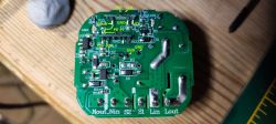
    You can see the module only has pins 7, 8, 24 and 26 soldered to the PCB, which covers all the Easy Flasher detected assignments
    Code: Text
    Log in, to see the code


    Circuit board of a switch with marked pins and elements like RELAY, GND, P8, P7, VCC, KEY, LED.

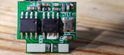
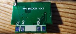
    Of greater interest though it the second module with two chips and an aerial. The module is marked as WH_RXD05 V0.2 and has pins marked as VCC, GND, RELAY (misspelled "REALY") , KEY and LED. The LED is red, whereas the LED on the mainboard is blue.
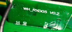
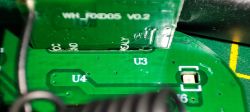
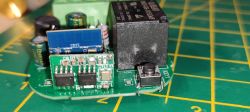
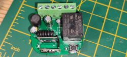
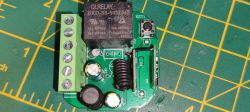
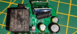
    Close-up of an electronic module labeled WH_RXD05 V0.2. Close-up of a circuit board with WH_RXD05 V0.2 module showing pin labels. RF module WH_RXD05 V0.2 with two chips and a red LED. WH_RXD05 V0.2 module on a wooden surface. CB2S module on a circuit board with a relay and a button. Image of an electronic module with green connectors, a relay, and other components. Top view of a circuit board with a relay, capacitors, and an antenna. Top view of a circuit board with electronic components and a coil antenna.

    The 2 8-pin chips on the RF module are labelled
    Code: Text
    Log in, to see the code
    and
    Code: Text
    Log in, to see the code

    The FMD appears to be a 1KB 2V~5.5V 64Byte 16MHz FLASH 6 SOP-8 MCU by Fremont Micro Devices - translated datasheet attached.
    The other chip, which only has 6 of the 8 pins soldered, is unknown, I have not been able to find any information about it. Some external memory perhaps?

    I do not have an RF remote of the correct frequency so cannot test the RF capabilities, but as far as I can tell only the relay on P8 is shared between the CB2S and the RF module, it seems to not have any communication with the CB2S. Paired with the Tuya app there is no mention of RF.
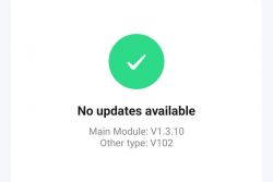
    Device screen message indicating no updates available, with main module version V1.3.10. Appearance of the app interface for controlling a smart switch.

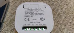
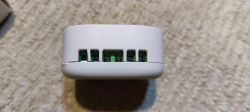
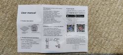
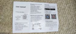
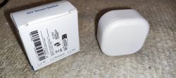
    Some pics of packaging and externals
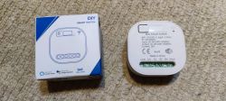
    Mini smart switch Tuya with packaging Close-up of the label on a mini smart switch detailing technical specifications. Square white casing of a mini switch with ventilation slots. Label of Tuya WiFi 15A Mini Smart Switch User manual with description and technical specifications of the Wi-Fi and RF remote control switch. Instruction manual for WiFi + RF 433 MHz receiver. User manual for a smart switch with RF 433 MHz functionality. DIY Smart Switch packaging and device on a carpet.

    OBK Template

    Code: JSON
    Log in, to see the code


    JSON

    Code: JSON
    Log in, to see the code
  • ADVERTISEMENT
  • #2 21000529
    divadiow
    Level 35  
    https://github.com/OpenBekenIOT/webapp/pull/84

    Added after 9 [hours]:

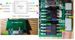
    Diagram of FT60F011A chip and image of WH_RXD05 V0.2 module.

    I've done a little more digging on the RF module and these traces appear correct. The unknown 8 pin chip seems to have 2 + and two ground lines. As far as I can tell only PA2 from the FMD is connected to it.
  • #3 21474565
    mohammedfonseca
    Level 1  
    >>21000525 would it be possible to control it with a CC1101 plugged to an arduino uno ? I tried several sketches with help of AI but nothing works. I can't receive any signal from the Wall Switch controlling this kind of Smart Switch.

    Example
    #include <SPI.h>

    #define CC1101_CS_PIN 10
    #define CC1101_GDO0_PIN 2

    volatile boolean received = false;
    volatile unsigned long pulseLength = 0;
    volatile unsigned long lastTime = 0;
    volatile byte pulseCounts = 0;
    volatile unsigned long pulseLengths[255];

    void setup() {
    Serial.begin(9600);
    while (!Serial);

    Serial.println("433MHz Signal Analyzer");

    // Initialize SPI
    SPI.begin();

    // Configure CC1101
    pinMode(CC1101_CS_PIN, OUTPUT);
    digitalWrite(CC1101_CS_PIN, HIGH);

    // Initialize CC1101
    configureCC1101();

    // Setup interrupt for receiving
    pinMode(CC1101_GDO0_PIN, INPUT);
    attachInterrupt(digitalPinToInterrupt(CC1101_GDO0_PIN), handleInterrupt, CHANGE);

    Serial.println("Waiting for 433MHz signals...");
    }

    void loop() {
    if (received) {
    Serial.println("Signal received!");

    // Print pulse timings
    for (int i = 0; i < pulseCounts; i++) {
    Serial.print(pulseLengths);
    Serial.print(" ");
    if ((i + 1) % 16 == 0) {
    Serial.println();
    }
    }
    Serial.println();

    // Analyze the pulse pattern
    analyzeSignal();

    // Reset for next capture
    pulseCounts = 0;
    received = false;

    // Enable interrupt again
    attachInterrupt(digitalPinToInterrupt(CC1101_GDO0_PIN), handleInterrupt, CHANGE);
    }

    delay(100);
    }

    void handleInterrupt() {
    unsigned long currentTime = micros();
    pulseLength = currentTime - lastTime;

    // Store pulse time if it's reasonable (to filter noise)
    if (pulseLength > 100 && pulseLength < 20000) {
    pulseLengths[pulseCounts++] = pulseLength;

    // If we've received enough pulses, consider it a signal
    if (pulseCounts >= 100) {
    detachInterrupt(digitalPinToInterrupt(CC1101_GDO0_PIN));
    received = true;
    }
    }

    lastTime = currentTime;
    }

    void analyzeSignal() {
    // Simple analysis to determine the protocol
    unsigned long shortPulse = 0;
    unsigned long longPulse = 0;

    // Find shortest and longest pulses
    for (int i = 0; i < pulseCounts; i++) {
    if (shortPulse == 0 || pulseLengths[i] < shortPulse) {
    shortPulse = pulseLengths[i];
    }
    if (pulseLengths[i] > longPulse) {
    longPulse = pulseLengths[i];
    }
    }

    Serial.print("Short pulse: ");
    Serial.print(shortPulse);
    Serial.print(" µs, Long pulse: ");
    Serial.print(longPulse);
    Serial.println(" µs");

    // Typical 433MHz encoding
    if (longPulse / shortPulse > 3) {
    Serial.println("Likely using protocol similar to RC-Switch");
    } else {
    Serial.println("Unknown encoding protocol");
    }
    }

    void configureCC1101() {
    // Reset
    writeRegister(0x30, 0x01);
    delay(10);

    // Configure for OOK modulation at 433.92 MHz
    writeRegister(0x02, 0x06); // IOCFG0: GDO0 Config
    writeRegister(0x0B, 0x06); // FSCTRL1: Frequency Synthesizer Control
    writeRegister(0x0D, 0x10); // FREQ2: Frequency Control Word, High Byte
    writeRegister(0x0E, 0xB1); // FREQ1: Frequency Control Word, Middle Byte
    writeRegister(0x0F, 0x3B); // FREQ0: Frequency Control Word, Low Byte
    writeRegister(0x10, 0x2D); // MDMCFG4: Modem Configuration
    writeRegister(0x11, 0x3B); // MDMCFG3: Modem Configuration
    writeRegister(0x12, 0x07); // MDMCFG2: Modem Configuration (OOK/ASK)
    writeRegister(0x13, 0x42); // MDMCFG1: Modem Configuration
    writeRegister(0x14, 0xF8); // MDMCFG0: Modem Configuration
    writeRegister(0x0C, 0x00); // FSCTRL0: Frequency Synthesizer Control

    // Set receive mode
    writeRegister(0x36, 0x01); // SIDLE
    delay(10);
    writeRegister(0x36, 0x02); // Set RX
    delay(10);
    }

    byte readRegister(byte reg) {
    digitalWrite(CC1101_CS_PIN, LOW);
    SPI.transfer(reg | 0x80);
    byte val = SPI.transfer(0);
    digitalWrite(CC1101_CS_PIN, HIGH);
    return val;
    }

    void writeRegister(byte reg, byte value) {
    digitalWrite(CC1101_CS_PIN, LOW);
    SPI.transfer(reg);
    SPI.transfer(value);
    digitalWrite(CC1101_CS_PIN, HIGH);
    }
    [/i][/i][/i][/i]
ADVERTISEMENT