logo elektroda
logo elektroda
X
logo elektroda

Using 433MHz RF Receiver with OpenBK on Smart Switch 4ch TYWB 4ch-RF Device

mbolty 6537 16
ADVERTISEMENT
  • #1 20656371
    mbolty
    Level 3  
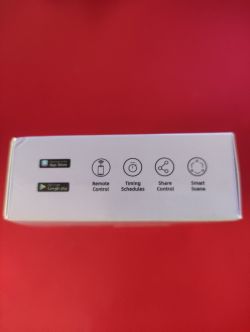
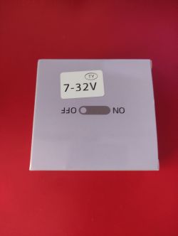
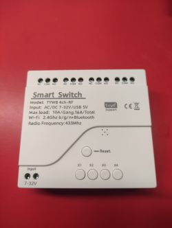
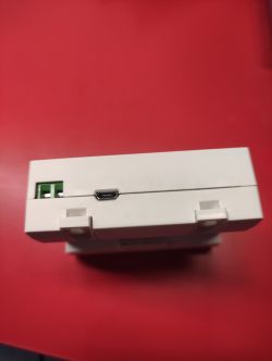
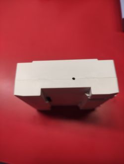
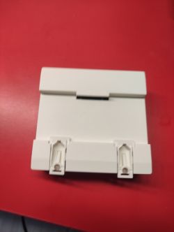
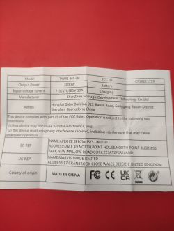
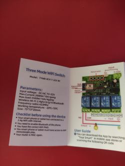
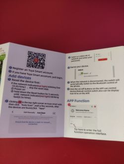
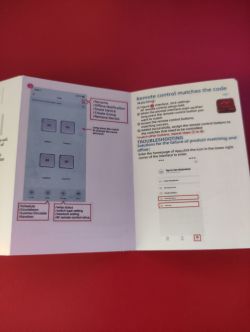
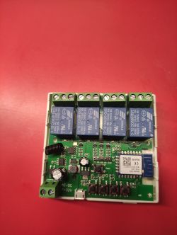
    Hello, I show you the device that I acquired and to which I installed openBK.
    This device comes with 433MHz RF receiver, but I was not able to get it to work with openBK.

    Using 433MHz RF Receiver with OpenBK on Smart Switch 4ch TYWB 4ch-RF Device Using 433MHz RF Receiver with OpenBK on Smart Switch 4ch TYWB 4ch-RF Device Using 433MHz RF Receiver with OpenBK on Smart Switch 4ch TYWB 4ch-RF Device Using 433MHz RF Receiver with OpenBK on Smart Switch 4ch TYWB 4ch-RF Device Using 433MHz RF Receiver with OpenBK on Smart Switch 4ch TYWB 4ch-RF Device Using 433MHz RF Receiver with OpenBK on Smart Switch 4ch TYWB 4ch-RF Device Using 433MHz RF Receiver with OpenBK on Smart Switch 4ch TYWB 4ch-RF Device Using 433MHz RF Receiver with OpenBK on Smart Switch 4ch TYWB 4ch-RF Device Using 433MHz RF Receiver with OpenBK on Smart Switch 4ch TYWB 4ch-RF Device
    Using 433MHz RF Receiver with OpenBK on Smart Switch 4ch TYWB 4ch-RF Device

    Using 433MHz RF Receiver with OpenBK on Smart Switch 4ch TYWB 4ch-RF Device
    Using 433MHz RF Receiver with OpenBK on Smart Switch 4ch TYWB 4ch-RF Device Using 433MHz RF Receiver with OpenBK on Smart Switch 4ch TYWB 4ch-RF Device
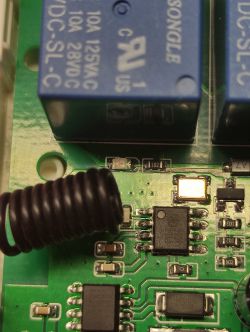
    In this image you can see the 433MHz RF chip.
    Using 433MHz RF Receiver with OpenBK on Smart Switch 4ch TYWB 4ch-RF Device

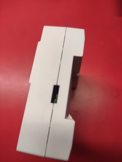
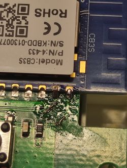
    Here you can see where I made the cut to be able to load the new firmware and then I had to repair it.
    Using 433MHz RF Receiver with OpenBK on Smart Switch 4ch TYWB 4ch-RF Device
    Using 433MHz RF Receiver with OpenBK on Smart Switch 4ch TYWB 4ch-RF Device Using 433MHz RF Receiver with OpenBK on Smart Switch 4ch TYWB 4ch-RF Device
    
    {
      "vendor": "Tuya",
      "bDetailed": "0",
      "name": "Samrt Switch",
      "model": "TYWB 4ch-RF",
      "chip": "BK7231N",
      "board": "CB3S",
      "flags": "136316032",
      "keywords": [
        "4 channels",
        "7-32V",
        "RF 433MHz",
        "5V"
      ],
      "pins": {
        "6": "Rel;2",
        "7": "Btn_Tgl_All;0",
        "8": "Btn;1",
        "9": "Btn;2",
        "10": "Btn;3",
        "11": "Btn;4",
        "14": "Rel;4",
        "20": "Rel;5",
        "22": "WifiLED_n;0",
        "24": "Rel;1",
        "26": "Rel;3"
      },
      "command": "",
      "image": "https://obrazki.elektroda.pl/5684118200_1689517857.jpg",
      "wiki": "https://www.elektroda.com/rtvforum/viewtopic.php?p=20656371#20656371"
    }
    
  • ADVERTISEMENT
  • #2 20658304
    p.kaczmarek2
    Moderator Smart Home

    Hello, where is the RF receiver connected? Does it connect to the GPIO of CB3S?
    Helpful post? Buy me a coffee.
  • #3 20660239
    mbolty
    Level 3  

    Yes, it is connected to P20. I configured it as a relay to see if when it was put in a high state it entered programming mode. But this didn't work.
  • ADVERTISEMENT
  • #4 20989959
    Pete0815
    Level 7  

    Hi
    any news regarding the 433MHz RF usage connected to P20? I'm planning to use also one of these boards.
    Worst-case scenario would be to replace the CB3S by ESP chip with Tasmota to make it happen. Anybody any experience doing so?

    Thx!
  • #5 20990053
    p.kaczmarek2
    Moderator Smart Home
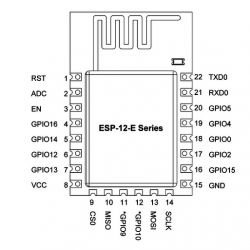
    I don't have this chip right now, but you can easily do swap to ESP12F module:
    Pin diagram of ESP-12-E module
    Here is sample "brain transplant" topic: Replacing the WiFi module with ESP12F (ESP8266) in a smart / tuya device
    Here is a guide for desoldering module with low quality, low power hot air station:


    If your module has two rows of pins soldered, then you can also use soldering iron trick:


    Alternatively you can wait for it to get supported, I'll ping this thread once we support that.
    Helpful post? Buy me a coffee.
  • #6 21011142
    Pete0815
    Level 7  
    Thank you very much and tried to replace by ESP8266 12F and like to share my experience.

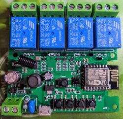
    Circuit board with ESP8266 module, four blue relays, and other electronic components.

    3 issues by doing a simple 1:1 replacement.

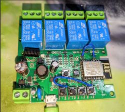
    1) On the board the Pin #3 means Enable (EN) is not pulled to continuous HIGH level (3,3V) which is essential for ESP8266 12F to work. Simple solution put a bridge from 3,3V to this PIN

    2) GPIO15 from ESP8266 12F is not pulled LOW (GND) on this board so the ESP-chip does not boot from Flash. Simple solution bridge GPIO15 to GND

    3) Problem because of GPIO15 is used for Button 4 you have to isolate the soldering pad from the board and GPIO 15 (e.g. put a piece of plastic in between). To make button 4 work again you can bring in a bridge from Button 4 to GPIO 0. This works and in addition you have an option to pull GPIO 0 to LOW (GND) in case you want to flash the chip again (OTA is of course is my preferred solution so don´t need this one).

    bridging Button 4 to GPIO 02 will not work for me because in many cases it´s used for a wifi LED and so there is disturbance.

    Using this confguration, be careful what to use relay 4 for, because GPIO 16 is pulled High during boot and this will shortly switch on/off relay 4 during boot.

    Close-up of a circuit board with an ESP8266 module and four blue relays.

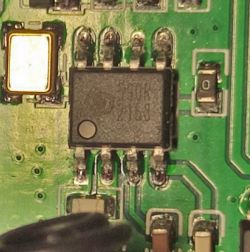
    In addition I tried to make RF function work at GPIO 10 by using Tasmota RF Transceiver Options but no RF signals can be seen in the console. Because of unprinted SOT8 RF chip on my board I´m interested in your experience about this chip and maybe we can find out what it is?

    Thanks in advance

    As example I also found this printed chip but no idea what it is:
    Close-up of an integrated circuit and surrounding components on a green printed circuit board.
  • #7 21011181
    divadiow
    Level 34  
    Pete0815 wrote:
    As example I also found this printed chip but no idea what it is:


    looks like a Synoxo SYN590R RF thingy

    Key Specifications/ Special Features:
    SYN590RD SYN590RL SYN590R
    SYNOXO RF IC electronic component
    SYN590R Features
    ----Frequency range: 300MHz ~ 450MHz
    ----Receive sensitivity: -110dBm (Typical)
    ---- Image Reject Mixer: 20dB (Typical)
    ----Receive bandwidth: 400KHz ~ 600KHz
    ---- Voltage range: 2.6V ~ 5.5V
    ---- Low power consumption: under 5V application
    --Typical 3.5mA (315MHz)
    --Typical 4.6mA (433.92MHz)
    --Typical 0.8uA (Shut Down)
    ---- No AGC capacitor required
    ---- Maximum data rate 5kbps
    ---- RoHS Compliant
    ---- SOP-8 package
  • #8 21011211
    p.kaczmarek2
    Moderator Smart Home
    I think we need to consult Tasmota docs for that: https://tasmota.github.io/docs/RF-Protocol/
    Helpful post? Buy me a coffee.
  • ADVERTISEMENT
  • Helpful post
    #9 21011439
    Pete0815
    Level 7  

    Thanks for your feedback. Maybe I'm struggling because of GPIO 10 which is connected to Flash on ESP8266.
    Will test with other GPIO and maybe we'll see if RF communication of Tasmota works with this SYNOXO RF chip.

    all tests so far have been done with RfProtocol enabled for Tasmota RF Receiver configuration.

    Will let you know about the outcome of my simple testing.

    Added after 2 [hours] 18 [minutes]:
    Edit:

    ok, done and it works. Testing with GPIO05 instead of GPIO10 leads me to identification of a loose contact at GPIO10.

    So resoldered and GPIO 10 is also fine for RF communication with Tasmota.

    09:30:46.653 RSL: RESULT = {"Time":"2024-03-20T09:30:46","RfReceived":{"Data":"0x5B9xxx","Bits":24,"Protocol":1,"Pulse":374}}
    

    Hope you can also benefit from this information.
  • #10 21018960
    Pete0815
    Level 7  
    Hi
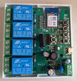
    there seems to be also a Ver.:2.0 available with slightly adjusted board layout now including J3Y NPN transistors for the relays:
    Circuit board with four blue relays and electronic components.
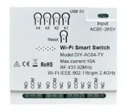
    and also slightly different housing:
    Wi-Fi smart switch model DIY-AC04-TY

    Edit:

    GPIO Assignment figured out based on ESP8266 12F:
    Button1: GPIO15 (not to be used for ESP8266 I used GPIO0 instead)
    Button2: GPIO05
    Button3: GPIO03
    Button4: GPIO01
    Button5(Reset): GPIO04
    Relay1: GPIO13
    Relay2: GPIO12
    Relay3: GPIO14
    Relay4: GPIO16
    RF_Receiver: GPIO10

    Wifi_LED: GPIO07 (unconfigured)

    To make it easy use template:
    {"NAME":"4ch-RF","GPIO":[64,67,0,66,1,65,0,1152,225,224,226,0,227,0],"FLAG":0,"BASE":18}
  • #11 21310939
    iarcaromica
    Level 3  
    Hi,
    I'm new in OpenBK and flashing Tuya chips. So please be patient with me, I would like to flash my TYWB 4ch RF, but I encounter issues. Please see below some pictures with the device.

    I have wires connected to the following pins:

    GND - black
    TXD1 - gray
    RXD1 - white
    TXD2 - yellow

    From the documentation here: https://developer.tuya.com/en/docs/iot/cb3s?id=Kai94mec0s076

    GND is reference ground
    TXD1 is UART1_TXD - connect to RX pin of my USB to TTL convertor
    RXD1 is UART1_TXD - connect to the TX pin of my USB to TTL convertor
    TXD2 is UART2_TXD (used to display the module internal information), which corresponds to P0 of the IC

    The issue is that I have no output when I have connected the USB to TTL convertor TXD1 and RXD1 (so I cannot write the firmware)
    If I connect TXD2 to the RX pin of my USB to TTL convertor, I can see some debugging output.

    
    V:BK7231N_1.0.1
    
    REG:cpsr     spsr     r13      r14
    
    SVC:000000D3          00401C1C 000033AC
    
    IRQ:000000d2 00000010 00401e0c 71b2dfa8 
    
    FIR:000000d1 00000010 00401ffc dabea36d 
    
    SYS:000000df          0040192c 00000158 
    
    ST:00000000
    
    J 0x10000
    
    bk_misc_init_start_type 0 0
    
    prvHeapInit-start addr:0x4111b0, size:126544
    
    [Flash]id:0xeb6015
    
    [01-01 18:12:15 TUYA I][lr:0xa584d] mqc app init ...
    
    [01-01 18:12:15 TUYA I][lr:0xb087b] thread_create name:sys_timer,stackDepth:4096,totalstackDepth:4096,priority:5
    
    [01-01 18:12:15 TUYA I][lr:0xb087b] thread_create name:cmmod,stackDepth:4096,totalstackDepth:8192,priority:4
    
    [01-01 18:12:15 TUYA D][lr:0xa5767] mq_pro:5 cnt:1
    
    [01-01 18:12:15 TUYA D][lr:0xa5767] mq_pro:31 cnt:2
    
    [01-01 18:12:15 TUYA D][lr:0xd402f] svc online log init success
    
    [01-01 18:12:15 TUYA D][lr:0xb0707] Thread:sys_timer Exec Start. Set to Running Stat
    
    [01-01 18:12:15 TUYA D][lr:0xcca0b] read m:0 f:0 l:0
    
    [01-01 18:12:15 TUYA I][lr:0xb087b] thread_create name:wk_th-0,stackDepth:5120,totalstackDepth:13312,priority:3
    
    [01-01 18:12:15 TUYA E][lr:0xb47e9] wd_protected_read fails gw_bi -23
    
    [01-01 18:12:15 TUYA D][lr:0xb4a5b] gw base read finish:-23
    
    [01-01 18:12:15 TUYA D][lr:0xd1beb] ty bt cmmod regist ok:1
    
    dev id key: 16
    
    d4 1d 8c d9 8f 00 b2 04 e9 80 09 98 ec f8 42 7e 
    
    [PLATFORM DEBUG]bt_port_init
    
    [01-01 ble mac:c4-82-e1-42-fa-18:12:15 TUYA N][lr:0xa52
    
    !!!!!!init_type=0
    
    1d65] ble sdk re_inited[ble_appm_send_gapm_res
    
    [01-01 18:12:15 TUYA et_cmd]
    
    !!!!!!init_type=1
    
    llm_init:312
    
    D][lr[gapm_cmp_evt_handler] :0xd2651] bt active iniconidx:0,operation:0x1,t
    
    [01-01 18:12:15 TUYAstatus:0x0
    
    cmd->addr.a N][lr:0xd1cd9] ty bt sddr[5] :0
    
    ype=2!init_tdk init success finish
    
    [gapm_cmp_evt_han
    
                     [01-01 18:12:15 TUYA Ndler] conidx:0,operatio][lr:0x5cb9b] --- pre_dn:0x3,status:0x0
    
    gapm_evice_init:59 ---
    
    cmp_evt:GAPM_SET_DEV_CONFIG
    
    gapm_cmp_evt:wait GAPM_GEN_RAND_NB
    
    [gapm_cmp_evt_handler] conidx:0,operation:0x1a,status:0x0
    
    gapm_cmp_evt:GAPM_GEN_RAND_NB
    
    [gapm_cmp_evt_handler] conidx:0,operation:0x1a,status:0x0
    
    gapm_cmp_evt:GAPM_GEN_RAND_NB
    
    [gapm_cmp_evt_handler] conidx:0,operation:0x28,status:0x0
    
    gapm_cmp_evt:BLE_STACK_OK
    
    [PLATFORM NOTICE]STACK INIT OK
    
    ble create new db
    
    ble_env->start_hdl = 0x10
    
    [PLATFORM NOTICE]CREATE DB OK
    
    adv_state:1
    
    [gapm_cmp_evt_handler] conidx:0,operation:0x1b,status:0x0
    
    adv_actv_idx:0,tx_pwr:0
    
    [PLATFORM DEBUG]UNKNOW EVENT:17
    
    [gapm_cmp_evt_handler] conidx:0,operation:0xa0,status:0x0
    
    [appm_adv_fsm_next] cur adv_state:1
    
    adv_state:2
    
    [ble_appm_set_adv_data]set data
    
    end adv_state:2
    
    [PLATFORM DEBUG]UNKNOW EVENT:16
    
    [gapm_cmp_evt_handler] conidx:0,operation:0xa9,status:0x0
    
    [appm_adv_fsm_n[01-01 18:12:15 TUYA N]ext] cur adv_state:2
    
    a[lr:0x5d0ff] find led[1]dv_state:3
    
    end adv_sta_lv none
    
    [01-01 18:12:te:3
    
    [PLATFORM DEBUG]U15 TUYA N][lr:0x5d12f] NKNOW EVENT:16
    
    [gapm_cfind led[1]_pin none
    
    mp_evt_handler] conidx:0,operation:0xaa,status:0x0
    
    [appm_adv_fsm_next][01-01 18:12:15 TUYA N] cur adv_state:3
    
    adv_s[lr:0x5d0ff] find led[2tate:6
    
    [ble_appm_start]_lv none
    
    [01-01 18:12_advertising]
    
    end adv_:15 TUYA N][lr:0x5d12f]state:6
    
    [PLATFORM DEBU find led[2]_pin none
    
    G]UNKNOW EVENT:16
    
    [gapm_cmp_evt_handler] conidx:0,operation:0xa4,status:0x0
    
    [appm_adv_fsm_next] cur adv_state:6
    
    a[01-01 18:12:15 TUYA N]dv_state:7
    
    end adv_sta[lr:0x5d0ff] find led[3te:7
    
    [PLATFORM DEBUG]UN]_lv none
    
    [01-01 18:12KNOW EVENT:16
    
    :15 TUYA N][lr:0x5d12f] find led[3]_pin none
    
    [01-01 18:12:15 TUYA N][lr:0x5d0ff] find led[4]_lv none
    
    [01-01 18:12:15 TUYA N][lr:0x5d12f] find led[4]_pin none
    
    [01-01 18:12:15 TUYA N][lr:0x5d265] channel init success
    
    [01-01 18:12:15 TUYA N][lr:0x601c3] reset type:1
    
    [PLATFORM NOTICE]bk_rst:0 tuya_rst:0
    
    [01-01 18:12:15 TUYA N][lr:0xca9c7] key_addr: 0x1ee000   block_sz 4096
    
    [01-01 18:12:15 TUYA N][lr:0xcaa97] get key:
    
    0xdb 0xe5 0xf5 0xde 0x2a 0x14 0x41 0x6a 0xbe 0x3e 0xfa 0x8d 0xb6 0x43 0xbe 0xf8 
    
    [01-01 18:12:15 TUYA N][lr:0x9fea3] have actived over 15 min, not enter mf_init
    
    [01-01 18:12:15 TUYA N][lr:0x5c9bd] mf_init succ
    
    [01-01 18:12:15 TUYA N][lr:0x5cbc3] --- app_init:243 ---
    
    [01-01 18:12:15 TUYA N][lr:0x5cbcf] < TUYA IOT SDK V:2.3.3 BS:40.00_PT:2.2_LAN:3.4_CAD:1.0.5_CD:1.0.0 >
    
    < BUILD AT:2022_12_07_15_29_01 BY ci_manage FOR ty_iot_sdk AT bk7231n >
    
    IOT DEFS < WIFI_GW:1 DEBUG:1 KV_FILE:0 SHUTDOWN_MODE:0 LITTLE_END:1 TLS_MODE:2 ENABLE_CLOUD_OPERATION:0 OPERATING_SYSTEM:2 ENABLE_SYS_RPC:0 RELIABLE_TRANSFER:0 ENABLE_LAN_ENCRYPTION:1 ENABLE_LAN_LINKAGE:0 ENABLE_LAN_DEV:0 >


    [01-01 18:12:15 TUYA N][lr:0x5cbd9] oem_bk7231n_control_switch:1.3.10
    
    [01-01 18:12:15 TUYA N][lr:0x5cbe3] firmware compiled at Dec 12 2022 14:09:13
    
    [PLATFORM NOTICE]bk_rst:0 tuya_rst:0
    
    [01-01 18:12:15 TUYA N][lr:0x5cbef] system restart reason is:0
    
    [01-01 18:12:15 TUYA N][lr:0x603b7] json cfg:[,rl1_lv:1,bt1_pin:8,net_trig:4,netled1_lv:0,onoff_rst_type:0,ffc_select:0,total_bt_pin:7,nety_led:1,total_stat:2,bt1_lv:0,remote_add_dp:49,remote_list_dp:50,rf_width:345,module:CB3S,inch_en4:0,inch_en2:0,inch_en3:0,inch_en1:0,rl2_pin:6,series_ctrl:0,bt_self_type:0,cyc_dpid:43,bt2_lv:0,rl1_pin:24,rl4_lv:1,onoff_rst_m:0,rl3_pin:26,rl3_lv:1,rand_dpid:42,rl4_pin:14,jv:110.0.0,key_rst_en:0,bt3_lv:0,reset_t:5,netled1_pin:22,rl2_lv:1,net_type:0,bt4_pin:11,inch_dp:44,bt3_pin:10,ch_cddpid1:9,remote_io:20,init_conf:38,bt4_lv:0,zero_select:0,onoff_type:2,bt2_pin:9,ch_cddpid4:12,ch_cddpid2:10,ch_cddpid3:11,total_bt_lv:0,remote_select:1,ch_num:4,ch_dpid3:3,ch_dpid4:4,netn_led:0,ch_dpid1:1,ch_dpid2:2,crc:127,}ZZZZZZZ\ufffd\ufffdA]
    
    [01-01 18:12:15 TUYA N][lr:0x6117f] ctrl lock init
    
    ctrl lock arr[0]: 
    
    ctrl lock arr[1]: 
    
    ctrl lock arr[2]: 
    
    ctrl lock arr[3]: 
    
    ctrl lock channel arr[0]: 255 255 255 255 
    
    ctrl lock channel arr[1]: 255 255 255 255 
    
    ctrl lock channel arr[2]: 255 255 255 255 
    
    ctrl lock channel arr[3]: 255 255 255 255 
    
    [01-01 18:12:15 TUYA N][lr:0x5ff51] read stat: [POWER]:2
    
    ******* ch[0] *******
    
    [RELAY] - pin:24,	 io_drive:2
    
    [KEY] - pin:8,	 io_drive:1,	 type:0,	 long_press:5000
    
    ******* ch[1] *******
    
    [RELAY] - pin:6,	 io_drive:2
    
    [KEY] - pin:9,	 io_drive:1,	 type:0,	 long_press:5000
    
    ******* ch[2] *******
    
    [RELAY] - pin:26,	 io_drive:2
    
    [KEY] - pin:10,	 io_drive:1,	 type:0,	 long_press:5000
    
    ******* ch[3] *******
    
    [RELAY] - pin:14,	 io_drive:2
    
    [KEY] - pin:11,	 io_drive:1,	 type:0,	 long_press:5000


    ******* system *******
    
    [WIFI LED] - pin:22,	 io_drive:1
    
    [TOTAL KEY] - pin:7,	 io_drive:0,	 long_press:5
    
    [433 REMOTER] - pin:20,	 freq_min:345
    
    [WIFI MTHD]-5, [WIFI LED]-1, [KEY TRIG]-0


    [01-01 18:12:15 TUYA E][lr:0x566b7] OPRT_INVALID_PARM
    
    [01-01 18:12:15 TUYA E][lr:0x566b7] OPRT_INVALID_PARM
    
    [01-01 18:12:15 TUYA E][lr:0x566b7] OPRT_INVALID_PARM
    
    [01-01 18:12:15 TUYA E][lr:0x566b7] OPRT_INVALID_PARM
    
    [01-01 18:12:15 TUYA N][lr:0x600c5] read stat:[KEY_TYPE]:0
    
    [01-01 18:12:15 TUYA N][lr:0x600cf] device [onoff] init success.
    
    [01-01 18:12:15 TUYA N][lr:0x60409] app read_gw_wsm.nc_tp:[9][0]
    
    [load]bandgap_calm=0x67->0x27,vddig=4->5
    
    [bk]tx_txdesc_flush
    
    [FUNC]intc_init
    
    [FUNC]calibration_main
    
    gpio_level=1,txpwr_state=15
    
    get rfcali_mode:1
    
    DPLL Unlock
    
    DPLL Unlock
    
    DPLL Unlock
    
    DPLL Unlock
    
    DPLL Unlock
    
    DPLL Unlock
    
    calibration_main over
    
    temp in flash is:343
    
    xtal in flash is:78
    
    [FUNC]func_init_extended OVER
    
    Version:
    
    tcp_port:62642
    
    app_init finished
    
    [01-01 18:12:16 TUYA N][lr:0x5c9eb] have actived over 15min, don't scan prod test ssid
    
    [01-01 18:12:16 TUYA N][lr:0x5cc4f] --- device_init start:616! remain heap:66072---
    
    [01-01 18:12:16 TUYA N][lr:0xb9a53] wifi soc init. pid:keyjnuy4s3kre7m7 firmwarekey:keyjnuy4s3kre7m7 ver:1.3.10
    
    [PLATFORM NOTICE]bk_rst:0 tuya_rst:0
    
    [01-01 18:12:16 TUYA N][lr:0xb3c9b] Last reset reason: 0
    
    [01-01 18:12:16 TUYA N][lr:0xb3d77] serial_no:c482e142fa51
    
    rw_ieee80211_set_country code:
    
    code: CN
    
    channel: 1 - 13
    
    mode: MANUAL
    
    bk_wlan cca closed
    
    [01-01 18:12:16 TUYA N][lr:0xb3db5] gw_cntl.gw_wsm.stat:2
    
    [01-01 18:12:16 TUYA N][lr:0xb82c5] gw_cntl->gw_wsm.nc_tp:9
    
    [01-01 18:12:16 TUYA N][lr:0xb82cd] gw_cntl->gw_wsm.md:0
    
    [01-01 18:12:16 TUYA N][lr:0xb3f11] gw_cntl.gw_if.abi:0 input:0
    
    [01-01 18:12:16 TUYA N][lr:0xb3f1f] gw_cntl.gw_if.product_key:keyjnuy4s3kre7m7, input:keyjnuy4s3kre7m7
    
    [01-01 18:12:16 TUYA N][lr:0xb3f29] gw_cntl.gw_if.tp:0, input:0
    
    [01-01 18:12:16 TUYA N][lr:0xb3f39] gw_cntl.gw_if.firmware_key:keyjnuy4s3kre7m7, input:keyjnuy4s3kre7m7
    
    [01-01 18:12:16 TUYA N][lr:0xd1d57] ty bt upd product:keyjnuy4s3kre7m7 1
    
    [01-01 18:12:16 TUYA N][lr:0x57141] wd_common_read failed op_ret:-6
    
    [01-01 18:12:16 TUYA N][lr:0x57141] wd_common_read failed op_ret:-6
    
    [01-01 18:12:16 TUYA N][lr:0x581c9] start tuya_inch_time_init..
    
    [01-01 18:12:16 TUYA N][lr:0x5be65] remote list num:[2]
    
    [01-01 18:12:16 TUYA N][lr:0x5becf] analysis list message success!
    
    [01-01 18:12:16 TUYA N][lr:0x5bb9f] [433]-start_us:[183:233], short:[4:17], long:[14:34]
    
    [01-01 18:12:16 TUYA N][lr:0x5bc31] *** driver remote io:20, hard timer:0 ***
    
    [01-01 18:12:16 TUYA N][lr:0x5bc47] tuya driver remote init success
    
    [01-01 18:12:16 TUYA N][lr:0x5c4fd] [remote] init success! Ver:[1.0.0]
    
    [01-01 18:12:16 TUYA N][lr:0x60bdf] not have dltj!
    
    remote task init success
    
    [01-01 18:12:16 TUYA N][lr:0x5ccb5] --- device_init success:711! remain heap:39512 ---
    
    [sa_sta]MM_RESET_REQ
    
    [bk]tx_txdesc_flush
    
    [sa_sta]ME_CONFIG_REQ
    
    [sa_sta]ME_CHAN_CONFIG_REQ
    
    [sa_sta]MM_START_REQ
    
    fast_connect
    
    sizeof(wpa_supplicant)=928
    
    hapd_intf_add_vif,type:2, s:0, id:0
    
    wpa_dInit
    
    enter low level!
    
    mac c4:82:e1:42:fa:51
    
    leave low level!
    
    net_wlan_add_netif done!, vif_idx:0
    
    wpa_supplicant_req_scan
    
    Setting scan[retry16] request: 0.000000 sec
    
    wpa_supplicant_scan
    
    wpa_drv_scan
    
    ht in scan
    
    scan_start_req_handler
    
    [01-01 18:12:16 TUYwpa_driver_scan_start_cA N][lr:0x5ecbd] gw stab
    
    tus changed to 3
    
    00 00 02 02 00 02 04 00 02 06 00 3B 
    
    [01-01 18:12:16 TUYA E][lr:0x57fa9] inch_time_upload err:-3589
    
    [01-01 18:12:16 TUYA E][lr:0x57a75] param is err!
    
    [01-01 18:12:16 TUYA E][lr:0xc3147] devid:bf16f0b22da1b113aas5q6 dparr[0]:0 not find
    
    [01-01 18:12:16 TUYA E][lr:0x5735b] dev_report_dp_json_async err:-3589
    
    [01-01 18:12:16 TUYA E][lr:0x5735b] dev_report_dp_json_async err:-3589
    
    [01-01 18:12:16 TUYA N][lr:0xd1d8b] ty bt upd localkey
    
    [01-01 18:12:16 TUYA N][lr:0xa1c45] upd login key len:6
    
    dev id key: 16
    
    99 88 78 01 70 25 ba 31 7a 0e 2c 9b d7 83 ed e7 
    
    [PLATFORM DEBUG]bt rst adv
    
    adv_state:12
    
    [gapm_cmp_evt_handler] conidx:0,operation:0xa9,status:0x0
    
    [appm_adv_fsm_next] cur adv_state:c
    
    adv_state:13
    
    end adv_state:d
    
    [PLATFORM DEBUG]UNKNOW EVENT:19
    
    [PLATFORM DEBUG]UNKNOW EVENT:16
    
    [gapm_cmp_evt_handler] conidx:0,operation:0xaa,status:0x0
    
    [appm_adv_fsm_next] cur adv_state:d
    
    adv_state:7
    
    end adv_state:7
    
    [PLATFORM DEBUG]UNKNOW EVENT:20
    
    [PLATFORM DEBUG]UNKNOW EVENT:16
    
    [01-01 02:00:01 TUYA N][lr:0xa1a55] ble adv && resp changed
    
    wpa_driver_scan_cb
    
    Scan completed in 0.356000 seconds
    
    cipher2security 2 2 16 16
    
    cipher2security 2 2 16 16
    
    wpa_supplicant_connect
    
    Cancelling scan request
    
    wpa_driver_associate: auth_alg 0x1
    
    me_set_ps_disable:842 0 0 1 0 3
    
    sm_auth_send:1
    
    sm_auth_handler
    
    ht in assoc req
    
    sm_assoc_rsp_handler
    
    rc_init: station_id=0 format_mod=2 pre_type=0 short_gi=1 max_bw=0
    
    rc_init: nss_max=0 mcs_max=7 r_idx_min=0 r_idx_max=3 no_samples=10
    
    ---------SM_CONNECT_IND_ok
    
    Cancelling scan request
    
    WPA: TK 1e801083d8adec4400c2fe0c19d9707e
    
    new dtim period:2


    new ie: 0 : 4f 72 61 6e 67 65 2d 35 35 51 63 2d 32 2e 34 47 
    
    new ie: 1 : 82 84 8b 96 c 12 18 24 
    
    new ie: 3 : 6 
    
    new ie: 30 : 1 0 0 f ac 4 1 0 0 f ac 4 1 0 0 f ac 2 c 0 
    
    new ie: 2d : ed 1 1f ff ff 0 0 1 0 0 0 0 0 2c 1 1 0 0 0 0 0 0 0 0 0 0 


    sta_mgmt_add_key
    
    WPA: GTK 96b9aa7a156b4bb653d0167eccc99625
    
    ctrl_port_hdl:1
    
    me_set_ps_disable:842 0 0 0 0 3
    
    WLAN_EVENT_CONNECTED
    
    sta_ip_start


    configuring mlan(with DHCPc)dhcp_check_status_init_timer:20000
    
    ip_addr: 2100a8c0
    
    first enable sleep 
    
    me_send_ps_req 2 0 0
    
    set_ps_mode_cfm:965 1 4 0 3 255
    
    enter 0 ps,p:2 m:1 int:100 l:100!
    
    [01-01 02:00:02 TUYA N][lr:0xaf419] mqtt get serve ip success
    
    [01-01 02:00:02 TUYA N][lr:0x601f5] wifi stat --> 6
    
     dtim period:2 multi:1
    
    [01-01 02:00:02 TUYA N][lr:0xa6c57] ret = 0
    
    [01-01 02:00:02 TUYA N][lr:0xaf419] mqtt create success, begin to connect
    
    [01-01 02:00:03 TUYA N][lr:0x601f5] wifi stat --> 7
    
    [01-01 02:00:03 TUYA N][lr:0xa6c57] ret = 0
    
    [appm_stop_advertising]
    
    adv_state:8
    
    [ble_appm_stop_advertising]
    
    [01-01 02:00:04 TUYA N][lr:0xa1fd7] ble_sdk_send skip, no connect:4
    
    [PLATFORM DEBUG]UNKNOW EVENT:18
    
    [gapm_cmp_evt_handler] conidx:0,operation:0xa5,status:0x0
    
    [appm_adv_fsm_next] cur adv_state:8
    
    adv_state:10
    
    end adv_state:a
    
    [PLATFORM DEBUG]UNKNOW EVENT:16
    
    [gapm_cmp_evt_handler] conidx:0,operation:0xa7,status:0x0
    
    [appm_adv_fsm_next] cur adv_state:a
    
    adv_state:0
    
    end adv_state:0
    
    [PLATFORM DEBUG]UNKNOW EVENT:16
    
    [11-20 12:47:32 TUYA E][lr:0x57c7d] list is NULL!
    
    [11-20 12:47:32 TUYA E][lr:0x57c7d] list is NULL!
    
    [11-20 12:47:32 TUYA E][lr:0xd4ac1] uf_open netcfg_log err 8
    
    [PLATFORM NOTICE]bk_rst:0 tuya_rst:0
    
    [11-20 12:47:39 TUYA N][lr:0xa6c57] ret = 0
    
    [11-20 12:47:39 TUYA N][lr:0xa6c57] ret = 0
    
    [11-20 12:47:44 TUYA N][lr:0xd3107] Update Timer from cloud
    
    [11-20 12:47:44 TUYA N][lr:0xa6c57] ret = 0
    
    [11-20 12:47:44 TUYA N][lr:0xa6c57] ret = 0
    
    [11-20 12:47:45 TUYA E][lr:0xad411] result null


    Can anyone help me with this? I also tried to reset the device by shorting the RED wire to the GND, but I cannot see anything on TXD1

    Thank you!
  • ADVERTISEMENT
  • #12 21310965
    p.kaczmarek2
    Moderator Smart Home
    You don't need to see anything on the TXD1 in order to flash with our tool:
    https://github.com/openshwprojects/BK7231GUIFlashTool
    However, I remember @ArturAVS showing me this device and I think it has capacitors on RXD1 and TXD1, which are also used for buttons. Those capacitors most likely will have to be removed. You don't need to put them back.
    I've already had similiar issue here:


    Watch whole video, we were not able to flash the device until we removed capacitor from the UART pin which is also used for button.
    Helpful post? Buy me a coffee.
  • #13 21311022
    iarcaromica
    Level 3  
    It looks like with the multimeter in diode mode (beep mode) I found direct link from TXD1 to Grey marked capacitor and from RXD1 to white marked capacitor (see attached photo). So I should just remove them and it no need to add back after I finish (it will work fine after that, or is just a noise cancel capacitor).

    Thank you!
  • #14 21311169
    iarcaromica
    Level 3  
    >>21311022

    I have removed the capacitors and also the resistor nearby. When I press Do firmware backup, I receive the error

    
    Backup name has not been set, so output file will only contain flash type/date.
    Starting read!
    Read parms: start 0x00 (sector 0), len 0x200000 (0 sectors)
    Now is: Wednesday, November 20, 2024 1:13:34 PM.
    Flasher mode: BK7231N
    Going to open port: COM6.
    Serial port open exception: System.UnauthorizedAccessException: Access to the port 'COM6' is denied.
       at System.IO.Ports.InternalResources.WinIOError(Int32 errorCode, String str)
       at System.IO.Ports.SerialStream..ctor(String portName, Int32 baudRate, Parity parity, Int32 dataBits, StopBits stopBits, Int32 readTimeout, Int32 writeTimeout, Handshake handshake, Boolean dtrEnable, Boolean rtsEnable, Boolean discardNull, Byte parityReplace)
       at System.IO.Ports.SerialPort.Open()
       at BK7231Flasher.BK7231Flasher.openPort() in E:GitHubBK7231GUIFlashToolBK7231FlasherBK7231Flasher.cs:line 98
    Failed to open serial port!
    There was no result to save.


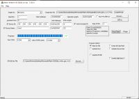
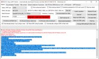
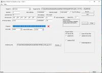
    When I run the Beken writer and hit the Read flash, it looks fine and it manages to get the flash (see the screens attached)

    LATER EDIT:
    I've managed to backup the firmware with your BK7231 Easy UART flasher. I'll come back soon as I try to push the new firmware.

    LATER EDIT 2: I've managed to flash the device. Is there any page where you can add the steps like a tutorial for others, or I should put here full steps that I followed. Thanks!

    Best regards!
  • #15 21438630
    rainerrmn
    Level 4  
    Hello,
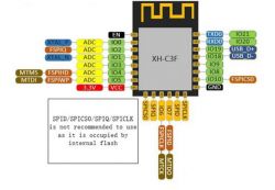
    I use an ESP32C3 in 12F-board like ESP32-C3FH4 from sparkle or aliexpress:
    ESP32-C3F pinout diagram with GPIO labels and pin functions.

    I flashed the ESP32C3F before installing, because you can not use UART0 or the USB D+/D- in the TYWB-board.
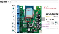
    Next step of preparision is to mount/weld 4 resistors as thombstones on the ESP. This ESP-Modul need 10k-pullup on GPIO8, GPIO9, GIO2 and EN/RST to boot from flash in this TYWB-board. On the TYWB these pads are empty.

    After removing the original CB3S i cut a wire between the signal-LED-resistor an the pad No. 18. After mounting the ESP32C3F, i made a connection to the pad No.19(GPIO6) instead.

    On the left side of ESP, there are 3.3V for the tops of the thombstones at EN (pad no. 1) and GPIO2 (pad no. 3) at pad No. 8 or at an capacitor nearby this pad.
    On the right side of the ESP, there are 3.3V for the tops of the thombstones at GPIO8 (pad no. 11) and GPIO9 (pad no. 12) nearby at the pullup-resistors for the buttons or at the votage regulator.

    ESP32-C3FH4 board with connections and labels on a relay module.

    RF is a SYN590 at GPIO7 (pad no. 20)
    Ledlink_i is at GPIO6 (pad no.19)
    GPIO18 (pad no. 13/USB-), GPIO10 (pad no. 10), GPIO20 (pad no. 15/RX0) and GPIO21(pad no.16/TX0) are button_n 1..4. Internal is a connector with COM/GND and this 4 Pins.

    ATTENTION: there is no galvanic isolation to the mains. With this knowledge, i remove the USB-Connector from the TYWB-board, so nobody can touch the mains-connected metal house of this connector. This connector is only for 5V-supply must strongly not be used, when mains connected.

    At GPIO19(pad no.14/USB+) is a button_n with "RESET"-label.

    GPIO1(pad no. 4), GPIO3(pad no. 5), GPIO4(pad no.7) and GPIO5(pad no. 6) are relay-outs. Each of them uses a transistor for driving the relais and a hard-connected signal-led. This signal-leds are useless, wenn the TYWB-board is in the case. If you want to use/see them with the controlled relais, you have to drill holes in the case over these leds.

    GPIO0, 2, 8, 9 (pads no. 2, 3, 11 and 12) are not used. same with th EN/RST at pad no.1.

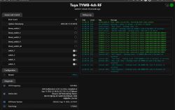
    I want to use this modul in a kitchen hood. the fan has 3 wires to select the speed and one wire is for the light. Later, i want to use the free GPIOs with a cheap thermal cam, a DHT11 or something like smoke-detector or fog-detector for automation. But for the first trial, i am fine with the "alexa"-matter-connect to my firetab in the kitchen. The ESP32C3 supports "matter" and in the tasmota-matter-config is a virtual fan endpoint, thats fits perfect for this.
  • #16 21448024
    rainerrmn
    Level 4  
    There is another name for a similar module: TYWB-4ch rf and TYWD-4ch rf. The difference between these modules is the supply voltage(AC-mains or low voltage-DC).
    The Beken CB3s, the rf SYN590, the 4 relays and buttons, the gpios used and all this are the same with these modules.

    So you can merge the information from the other thread:
    https://www.elektroda.com/rtvforum/topic4021221.html
  • #17 21582005
    spleefer90
    Level 7  
    I ended up just cutting the traces in the end, desoldering everything did not do it for me - it still leads to the pin header and I presume that one still has noise - I desoldered the brown(?) and black(10k resistors) components and the two buttons to no avail, thankfully I managed to put everything back.

    I did not think and I melted the plastic cover with hot air on one of my switches.

    Note that one of the pictures around the forum has the wrong RX/TX marking - refer to docs - https://developer.tuya.com/en/docs/iot/cb3s?id=Kai94mec0s076 - 15 RX; 16 TX

Topic summary

The discussion centers on integrating a 433MHz RF receiver with OpenBK firmware on the TYWB 4ch-RF smart switch, which uses a Beken CB3S WiFi module. Initial attempts to use the onboard SYN590R RF receiver connected to GPIO P20 failed. Users explored replacing the CB3S module with an ESP8266 ESP12F to enable RF functionality, encountering hardware challenges such as the need to pull ESP8266 EN pin high, pull GPIO15 low, and isolate GPIO15 from button circuitry. The SYN590R RF chip specifications were identified, and Tasmota firmware's RF protocol support was referenced as a potential solution. Successful RF reception was demonstrated using Tasmota with the RF receiver connected to GPIO10 after fixing a loose contact. Additional hardware notes include the presence of capacitors on UART RXD1/TXD1 lines that must be removed to enable flashing via USB-TTL converters. An alternative approach involved replacing the CB3S with an ESP32C3F module, requiring specific pull-up resistors on GPIOs for proper boot. The TYWB 4ch-RF and TYWD 4ch-RF modules share similar hardware except for power supply differences. GPIO assignments for relays, buttons, and RF receiver were mapped for ESP8266 12F. Users also reported issues with flashing permissions and hardware modifications such as cutting traces and desoldering components to reduce noise and enable stable operation. Documentation links and community resources were shared for further guidance.
Summary generated by the language model.
ADVERTISEMENT