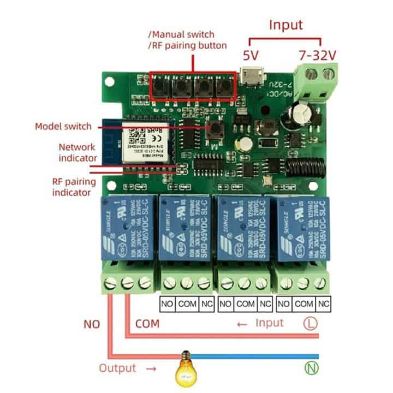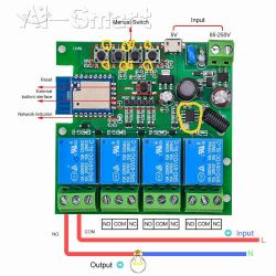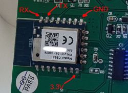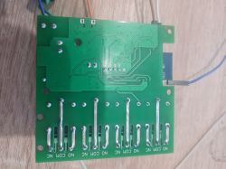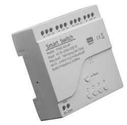
Hello,
Here is Tuya JSON config for this device:
Code: JSON
As exported by https://github.com/openshwprojects/BK7231GUIFlashTool :
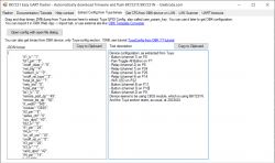
Text description:
Device configuration, as extracted from Tuya:
- Button (channel 1) on P8
- Pair/Toggle All Button on P7
- Relay (channel 2) on P6
- Relay (channel 1) on P24
- Relay (channel 3) on P26
- Relay (channel 4) on P14
- WiFi LED on P22
- Button (channel 4) on P11
- Button (channel 3) on P10
- Button (channel 2) on P9
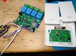
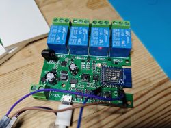
Device seems to be using CB3S module, which is using BK7231N.
And the Tuya section starts, as usual, at 2023424
OBK template:
Code: JSON
After desoldering the CB3S chip from the board, I successfully put ESPHome on this Relay Board:
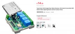
https://vi.aliexpress.com/item/10050053866410...1RO%21728730991%21&curPageLogUid=ruZlMkOZGwQc
I will leave here a 2 MB bin extracted and templates if anyone wants to put it on their board:
ADVERTISEMENT
GPIO for EspHome:
sensor:
  - platform: uptime
    name: Uptime

binary_sensor:
  - platform: gpio
    id: binary_switch_1
    pin:
      number: P8
      inverted: true
      mode: INPUT_PULLUP
    on_press:
      then:
        - switch.toggle: switch_1
  - platform: gpio
    id: binary_switch_2
    pin:
      number: P9
      inverted: true
      mode: INPUT_PULLUP
    on_press:
      then:
        - switch.toggle: switch_2
  - platform: gpio
    id: binary_switch_3
    pin:
      number: P10
      inverted: true
      mode: INPUT_PULLUP
    on_press:
      then:
        - switch.toggle: switch_3
  - platform: gpio
    id: binary_switch_4
    pin:
      number: P11
      inverted: true
      mode: INPUT_PULLUP
    on_press:
      then:
        - switch.toggle: switch_4
  - platform: gpio
    id: binary_switch_all
    pin:
      number: P7
      inverted: true
      mode: INPUT_PULLUP
    on_press:
      then:
        - switch.toggle: switch_1
        - switch.toggle: switch_2
        - switch.toggle: switch_3
        - switch.toggle: switch_4

switch:
  - platform: gpio
    id: switch_1
    name: Open Gate
    pin: P24
  - platform: gpio
    id: switch_2
    name: Close Gate
    pin: P6
  - platform: gpio
    id: switch_3
    name: Stop Gate
    pin: P26
  - platform: gpio
    id: switch_4
    name: Gate SbS
    pin: P14

status_led:
  pin:
    number: P22
    inverted: true
I forgot to take some pictures of the board.
Thanks


