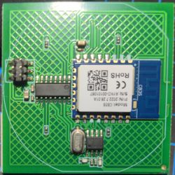
I purchased bunch of 4 Gang Smart Switches from Aliexpress:
https://vi.aliexpress.com/item/1005005859040019.html?

The device has CB3S module:

Tuya app recognized the device as W604-BLE.
There has been a cloudcutter profile for this device:
https://github.com/tuya-cloudcutter/tuya-clou...es/tuya-generic-ds-w604-ble-light-switch.json
Unfortunately the new devices come with FW V1.3.5 which has been patched.
So the only way now is to flash directly.
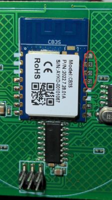
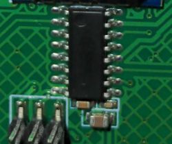
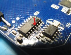
When you inspect the PCB I discovered that the RX pin is connected to the pin number 3 of the 14-pin chip. I do not know whether this is a simple button controller or a Tuya MCU device. The above cloudcutter profile indicates that the old device was a Tuya MCU based.
Unfortunately the PCB does not show any tracks that can be broken temporarlily to disconnect the RX pin.
Since I have a bunch of these switches to work on, I do not want to de-solder the modules completely.
I am wondering whether I can just heat up the pads and lift the module a little bit because not all the pins are actually soldered.

Any better suggestions?
https://vi.aliexpress.com/item/1005005859040019.html?

The device has CB3S module:

Tuya app recognized the device as W604-BLE.
There has been a cloudcutter profile for this device:
https://github.com/tuya-cloudcutter/tuya-clou...es/tuya-generic-ds-w604-ble-light-switch.json
Unfortunately the new devices come with FW V1.3.5 which has been patched.
So the only way now is to flash directly.
When you inspect the PCB I discovered that the RX pin is connected to the pin number 3 of the 14-pin chip. I do not know whether this is a simple button controller or a Tuya MCU device. The above cloudcutter profile indicates that the old device was a Tuya MCU based.
Unfortunately the PCB does not show any tracks that can be broken temporarlily to disconnect the RX pin.
Since I have a bunch of these switches to work on, I do not want to de-solder the modules completely.
I am wondering whether I can just heat up the pads and lift the module a little bit because not all the pins are actually soldered.

Any better suggestions?


