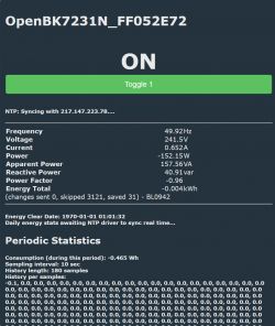
So this point are my observations on negative current measurements using tuya devices.
What's the deal about it? Well AC is constantly changing polarity, so in order to measure the flow of current, one needs to use the phase angle information, in addition to current and voltage. Many AC power meter's can't measure the direction of an AC current, they only report an absolute value, because... most devices only consume power!
Now, with PV Solar modules becoming common, it's interesting to be able to measure the current in both directions, to understand if one is consuming from the grid or exporting to the grid. If one is exporting, the rates are often so low that it is desirable to first try and consume this energy by activating certain loads such heating, or hot water heating which can be timed to come on when there is an excess of production, avoiding the consumption of excessive energy from the grid and promoting self consumption.
On the market there are many devices that feature a energy consumption feature. Most are based on the BL0937 and some on the BL0942. The BL0937 is an 8 pin device that uses a series of pulses to indicate the current flow. These can be reconstructed in a microcontroller to provide a representation of the actual current flow. These devices are the most common ones, but they are not able to indicate the direction of power, only it's absolute value. Another reason why you should stay away from them is because if deep sleep or power saving is enabled, pulses might be skipped and power readings will not be accurate.
Another device, which is not so common is the BL0942 - a fully serial programmable power monitor which provides details on power and direction and can therefore be used for measurements of energy in either direction. Chinese firmware programs the device in order to only obtain the absolute values of power, so to be able to measure it's direction, it is necessary to flash it with Open Becken.
The devices can be distinguished easily - The more common BL0937 is an 8 pin device, while the BL0942 is a 10 pin device.
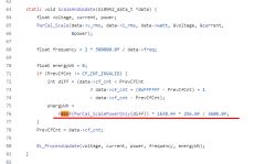
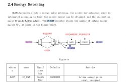
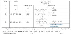
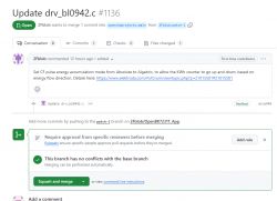
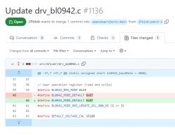
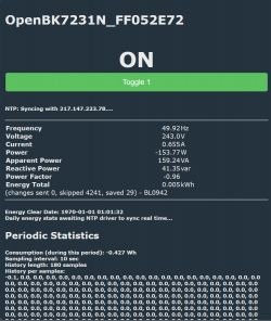
One challenge with OpenBecken is that even though instantaneous power is measured correctly as either a positive or negative value, cumulative power is not. The total KWh reading is always positive, so it simply adds consumption and export together as a single number, which is not very useful to monitor your solar installation or consumption over time.
I guess one solution would be to poll the instantaneous values and reconstruct the total consumption, but I'm pretty sure the BL0942 chip can be initialized to do this. If someone has an idea how to get to the source code on openbecken, please let me know. In the meanwhile, if time allows, I might just buy myself a pair of CC1101 dongles and use my choice of microcontroller to communicate directly with the BL0942. This would also solve the problem of the WiFi module, as most of my fuse boxes are metal and shielded / grounded, which kills the 2.4Ghz signal.
Here are some of the devices I found, which are based on the BL0942:
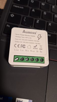
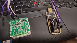
The Aubess is by far my favourite. The relay cuts the Neutral (So you can wire it bypassing the relay), Power save works fine, reducing self heating, it's cheap, easy to open and easy to program. But It's limited to 16A as the current must go through PCB traces, so it's a stretch to use it in an incoming house supply. Particularly, in case of short circuit, I don't know if the surface mounted sense resistor would survive.
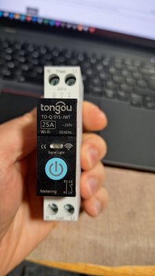
The Tongou TO-Q-SY1-JWT is possibly the most promising. The Relay is bystable (it keeps states without power), so that means a failure won't result in loss of power to the house. It is rated up to 63A and it's relatively easy to program once open. But I don't like that it is riveted and so, it's hard to close it back again. It also seems to draw 1W regardless of what, so I wonder about the durability of the caps inside, which run pretty hot. The power supply regulates at 12V, for the relay, and an LM1113 steps down the power to the WiFi module. So 3x it's consumption are just wasted as heat.
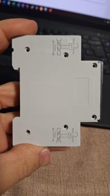
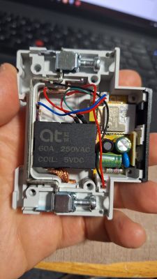
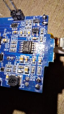
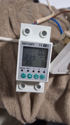
Another interesting device is The SMTONFF. It appears to be the same device covered (https://www.elektroda.com/rtvforum/ttopic4022907.html
The WB3S module has to be removed to program and it's obviously a larger device. There are others that can be programmed as the WiFi module can be de-attached from tuya MCU, releasing the Serial port. (https://www.elektroda.com/rtvforum/topic3995777.html and https://www.elektroda.com/rtvforum/topic3933839.html)
I am not fully sure how to read from the Tuya MCU - Who manages the communication with the BL0942 - guess I will figure that out.
This device can easily be opened (only two screws on the back), however, it relies on a relay that must be constantly powered, so a failure of the device will result in loss of power to the circuits downstream. The current measurement is inline with the relay, so no option to bypass without modifying it. It also heats up a bit inside, drawing the same 0.8W whenever the relay is on or off - I suspect some kind of current limited shunt power supply.
My version doesn't measure negative values, and since communication with the BL0942 is managed by the tuya MCU, I guess there is not much that can be done other than waiting for tuya to update it's firmware. I also found it annoying that the display shows KWh and instantaneous voltage and current, but not power.
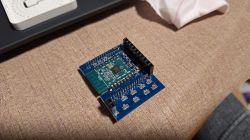
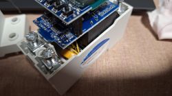
If you know of any additional devices based on the BL0942 or how to get under the hood on the programing of the BL0942 under Openbecken, please write here. I think we can all benefit. Meanwhile I will slowly update as I make modifications to the devices.
What's the deal about it? Well AC is constantly changing polarity, so in order to measure the flow of current, one needs to use the phase angle information, in addition to current and voltage. Many AC power meter's can't measure the direction of an AC current, they only report an absolute value, because... most devices only consume power!
Now, with PV Solar modules becoming common, it's interesting to be able to measure the current in both directions, to understand if one is consuming from the grid or exporting to the grid. If one is exporting, the rates are often so low that it is desirable to first try and consume this energy by activating certain loads such heating, or hot water heating which can be timed to come on when there is an excess of production, avoiding the consumption of excessive energy from the grid and promoting self consumption.
On the market there are many devices that feature a energy consumption feature. Most are based on the BL0937 and some on the BL0942. The BL0937 is an 8 pin device that uses a series of pulses to indicate the current flow. These can be reconstructed in a microcontroller to provide a representation of the actual current flow. These devices are the most common ones, but they are not able to indicate the direction of power, only it's absolute value. Another reason why you should stay away from them is because if deep sleep or power saving is enabled, pulses might be skipped and power readings will not be accurate.
Another device, which is not so common is the BL0942 - a fully serial programmable power monitor which provides details on power and direction and can therefore be used for measurements of energy in either direction. Chinese firmware programs the device in order to only obtain the absolute values of power, so to be able to measure it's direction, it is necessary to flash it with Open Becken.
The devices can be distinguished easily - The more common BL0937 is an 8 pin device, while the BL0942 is a 10 pin device.
One challenge with OpenBecken is that even though instantaneous power is measured correctly as either a positive or negative value, cumulative power is not. The total KWh reading is always positive, so it simply adds consumption and export together as a single number, which is not very useful to monitor your solar installation or consumption over time.
I guess one solution would be to poll the instantaneous values and reconstruct the total consumption, but I'm pretty sure the BL0942 chip can be initialized to do this. If someone has an idea how to get to the source code on openbecken, please let me know. In the meanwhile, if time allows, I might just buy myself a pair of CC1101 dongles and use my choice of microcontroller to communicate directly with the BL0942. This would also solve the problem of the WiFi module, as most of my fuse boxes are metal and shielded / grounded, which kills the 2.4Ghz signal.
Here are some of the devices I found, which are based on the BL0942:
The Aubess is by far my favourite. The relay cuts the Neutral (So you can wire it bypassing the relay), Power save works fine, reducing self heating, it's cheap, easy to open and easy to program. But It's limited to 16A as the current must go through PCB traces, so it's a stretch to use it in an incoming house supply. Particularly, in case of short circuit, I don't know if the surface mounted sense resistor would survive.


The Tongou TO-Q-SY1-JWT is possibly the most promising. The Relay is bystable (it keeps states without power), so that means a failure won't result in loss of power to the house. It is rated up to 63A and it's relatively easy to program once open. But I don't like that it is riveted and so, it's hard to close it back again. It also seems to draw 1W regardless of what, so I wonder about the durability of the caps inside, which run pretty hot. The power supply regulates at 12V, for the relay, and an LM1113 steps down the power to the WiFi module. So 3x it's consumption are just wasted as heat.


Another interesting device is The SMTONFF. It appears to be the same device covered (https://www.elektroda.com/rtvforum/ttopic4022907.html
The WB3S module has to be removed to program and it's obviously a larger device. There are others that can be programmed as the WiFi module can be de-attached from tuya MCU, releasing the Serial port. (https://www.elektroda.com/rtvforum/topic3995777.html and https://www.elektroda.com/rtvforum/topic3933839.html)
I am not fully sure how to read from the Tuya MCU - Who manages the communication with the BL0942 - guess I will figure that out.
This device can easily be opened (only two screws on the back), however, it relies on a relay that must be constantly powered, so a failure of the device will result in loss of power to the circuits downstream. The current measurement is inline with the relay, so no option to bypass without modifying it. It also heats up a bit inside, drawing the same 0.8W whenever the relay is on or off - I suspect some kind of current limited shunt power supply.
My version doesn't measure negative values, and since communication with the BL0942 is managed by the tuya MCU, I guess there is not much that can be done other than waiting for tuya to update it's firmware. I also found it annoying that the display shows KWh and instantaneous voltage and current, but not power.


If you know of any additional devices based on the BL0942 or how to get under the hood on the programing of the BL0942 under Openbecken, please write here. I think we can all benefit. Meanwhile I will slowly update as I make modifications to the devices.


